Dumping Firmware With the CH341a Programmer
Rick Wisser //
Note: This blog will also be a lab for any of the upcoming Wild West Hackin’ Fest Conferences.
During a recent engagement, I came across an issue. The issue I encountered was that the SPI chip I was trying to dump the firmware off of was a 1.8v chip. This would not have been a problem but both the shikra and bus pirate are rated for 3.3v chips. I considered creating a voltage divider to step the voltage down but after a little Googling, I came across the CH341a with the 1.8v adapter. I decided to order it with one-day shipping. After I worked with it and was able to successfully dump the firmware from the 1.8v IC without having to remove the SPI chip from the circuit board, I decided to write a blog about it. This blog is targeted for all audiences. It might be a little too step-by-step for intermediate or experienced people who have dumped firmware with other tools but I wanted to include the beginner as well because we all started somewhere right?
Below is a picture of the CH341a package that I got. I will include links at the end of this blog on which items I bought or reference.

The CH341a is very easy to set-up. Usually, I use a Linux variant Operating System for conducting any testing. However, from previous experience, I know that the AsProgrammer works better on a Windows PC. All you need are the drivers and the AsProgrammer software which can be found in the following links.
“CH341-Windows-SPI-I2C-Driver+SDK-library” and “CH341-Windows-Serial-Driver+SDK-library” directories at https://github.com/boseji/CH341-Store.
AsProgrammer software – https://github.com/nofeletru/UsbAsp-flash/releases/
After downloading the software and installing it on my Windows laptop, it was time to pick a target. I went into my collection of “garage sale” electronics and found a Netgear WNDR3700 router that would do the trick. After cracking open the case and conducting reconnaissance on the chips for the device, I found a target SPI chip. The following is a picture of the board with the SPI chip identified.
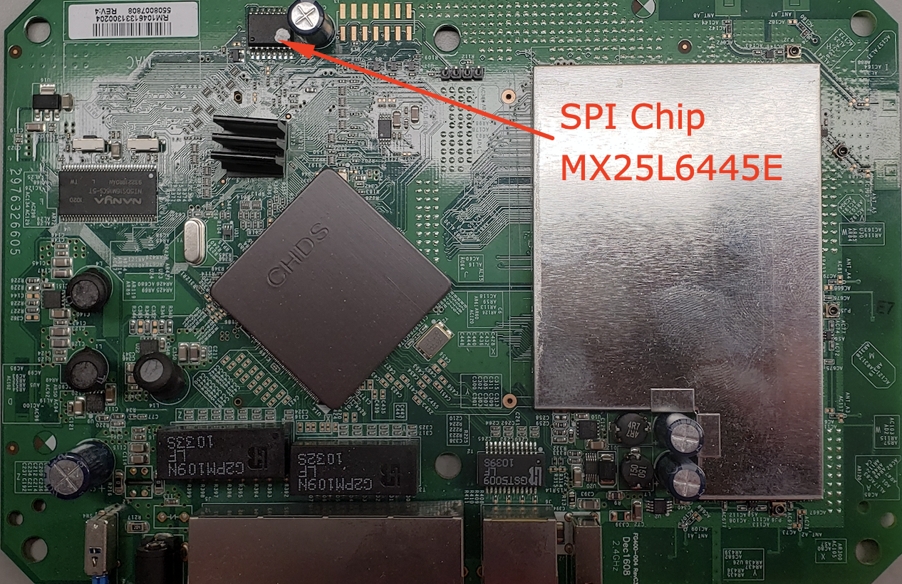
As with any reconnaissance, you will want to find more information. Therefore, I grabbed the datasheet for the MX25L6445E SPI chip and looked at the pin diagram and identified the type of package that is installed on the WNDR3700 circuit board.

Examining the datasheet, I noticed that this particular chip has a VCC of 3.3v and the actual package type on the board is a 16 pin chip. Due to this information, we know that it is not necessary to use the 1.8v adapter. But it appears that we might have an issue with the 16 pin chip package (note that the middle 8 pins are not used.) The CH341a only comes with an 8 pin chip clip and header. I could solder wires onto the functioning pins of the MX25L6445E and interface it to the CH341a Zero Insertion Force (ZIF) socket but since I could use a 16 pin chip clip for future engagements I decided to purchase one.
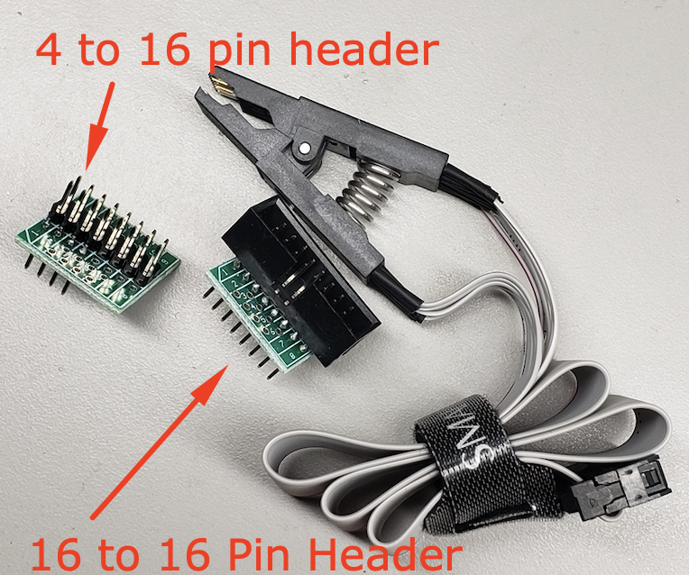
After a quick internet search, I chose a 16 pin chip clip that included headers already soldered for interfacing with the ZIF socket of the CH341a. I will place the link for the 16 pin chip clip at the bottom of this blog along with a link for the CH341a programmer. The headers that were provided with the 16 pin chip clip included an 8 to 16 pin as well as a 16 to 16 pin header. I also ohmed out the 8 to 16 pin header and found that it had the correct traces in place to interface directly with the 16 pin MX25L6445E chip and the CH341a ZIF socket. Here is a picture of the chip clip with the headers.
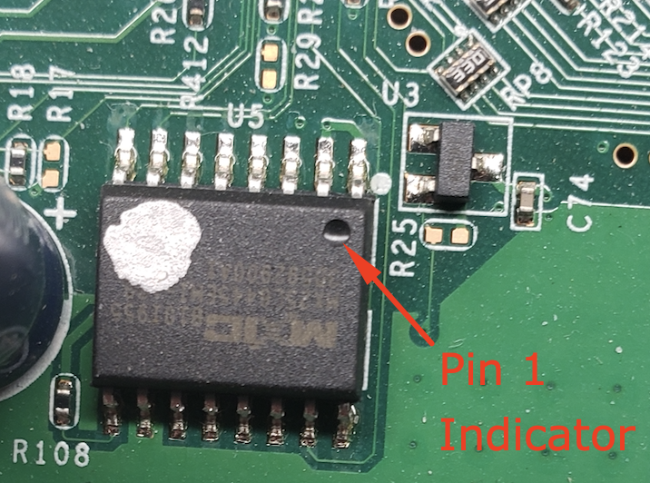
The connections were easy to make since everything has either pin markings, silkscreen prints, or some type of indicator to reference pin 1. For instance, the chip is marked with a divot in the corner where pin 1 is. The chip clip has one of its strands of cable red to indicate pin 1 and the interface board has numbers silk-screened on the board to indicate the pins. Finally, the CH341a has silkscreen as well to indicate where pin one goes for either a 24xxx or 25xxx chip type. Below are images with descriptions showing the pin and silk marking indicators.
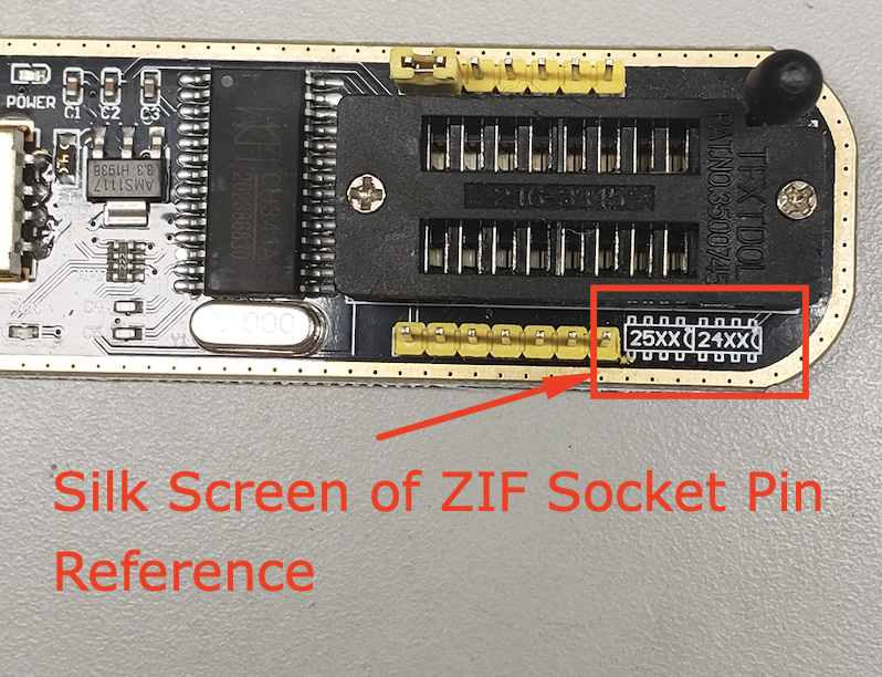
The CH341a silkscreen has indicators for 25xx and 24xx with little half circles to the right of them. This half-circle indicates that pin 1 is next to the half-circle and would be the top right corner. The ZIF socket has 16 pins so it is divided in half with the right side for 24xx chips and the left side for 25xx chips. In this situation, we will be using the left side of the ZIF socket since our chip is an MX25L6445E chip.
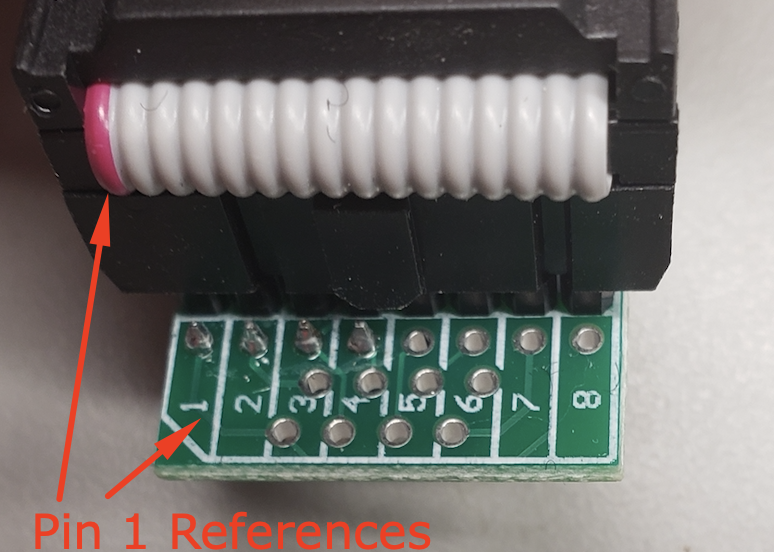
The above image shows the chip clip cable attached to the header board with the pin 1 designators lined up.
Next, we will hook the chip clip to the chip with the red pin 1 indicator aligned with the pin 1 designator of the MX25L6445E chip as shown below.

Finally, we install the header with the chip clip cable onto the CH341a ZIF socket as shown below.

Now with everything connected, we can dump the firmware from our MX25L6445E chip. We connect the CH341a to the USB port on our Windows PC and open up AsProgrammer. First, we have to select the CH341a as the hardware device in the Hardware menu.
IMPORTANT NOTE: The CH341a supplies the power to the board so you do not need to plug in the WNDR3700 into the wall. If you do so, you may damage your CH341a.

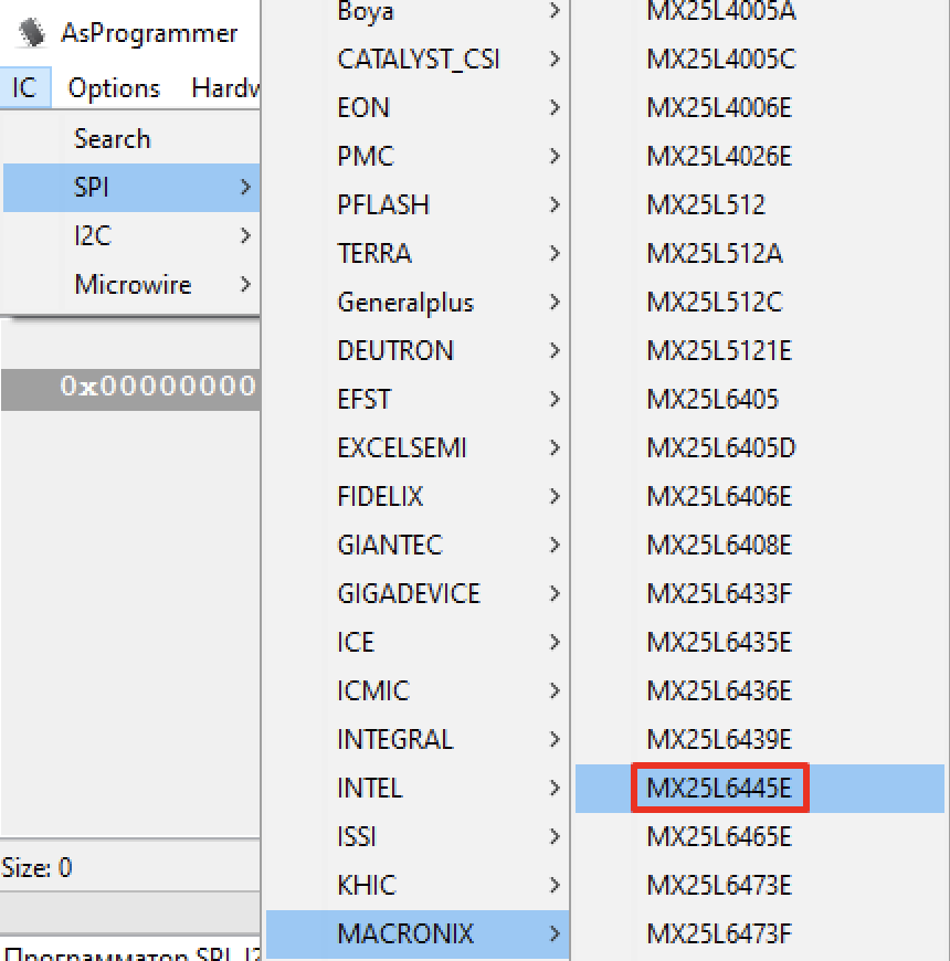
The next thing you need to do is select the type of SPI chip you will be using. Select IC from the main menu and then SPI followed by the vendor and then the IC. In this case, we want the MACRONIX MX25L6445E chip.
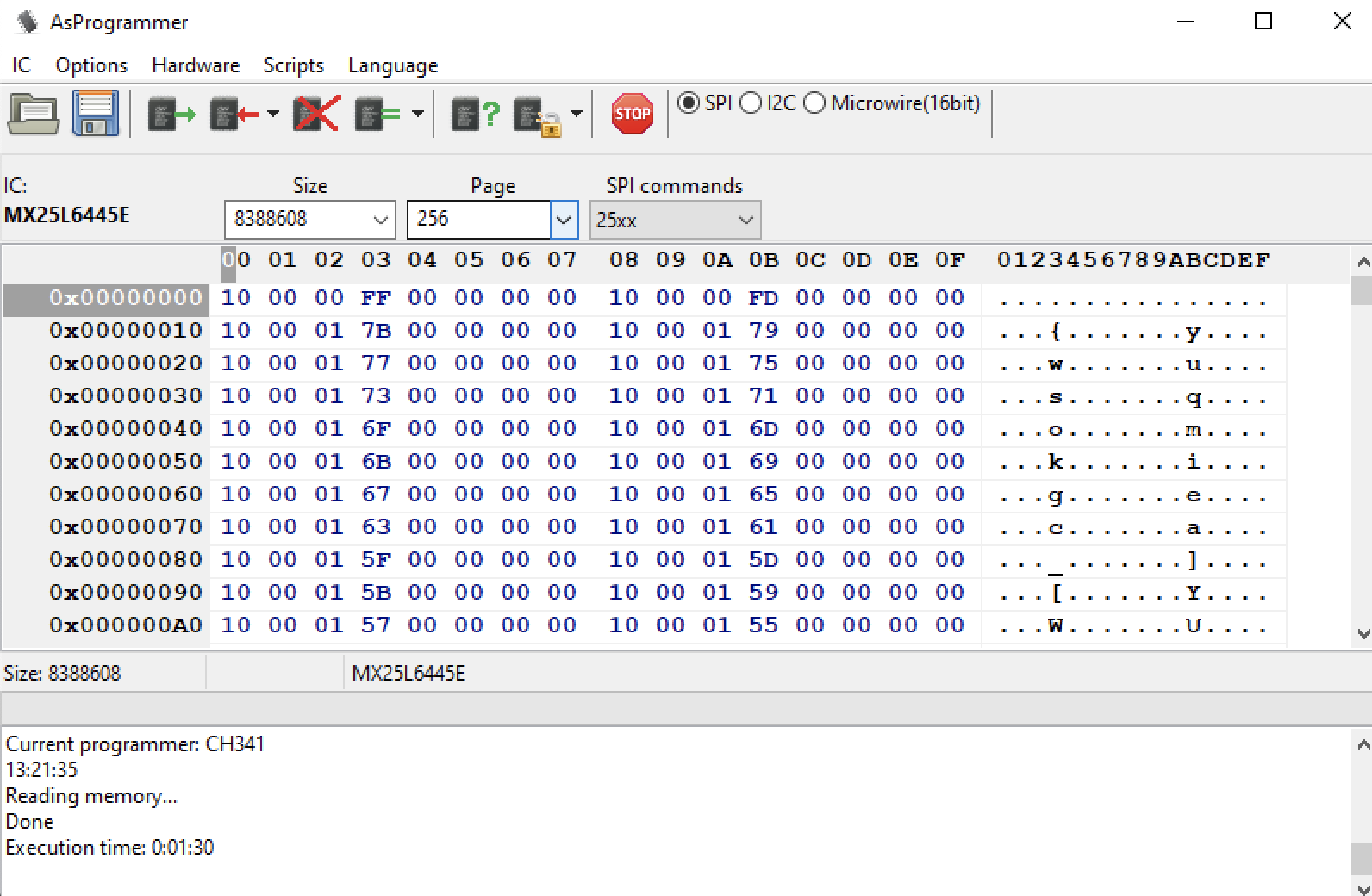
Once the chip is selected it will be shown in the top menu screen of the AsProgrammer. The “Size”, “Page”, and “SPI commands” will also auto-populate so you should not have to mess with them. You also want to confirm that the SPI radio button is selected. Below is a screenshot of how AsProgrammer should be set-up.

Once everything looks good you will click the box with the green arrow coming out of it to read the contents of the chip. Once it is done, you can also save it with the floppy disc icon.
This particular chip took 1.5 minutes to read the contents which can be shown below in the screenshot below after reading the contents of the MX25L6445E Chip.
Now that we have our firmware dumped we can evaluate it for anything of interest. In this case, I used the “strings” or “strings.exe” (You will have to download it for the Windows OS) to search for “password” and “SSID” as shown below.
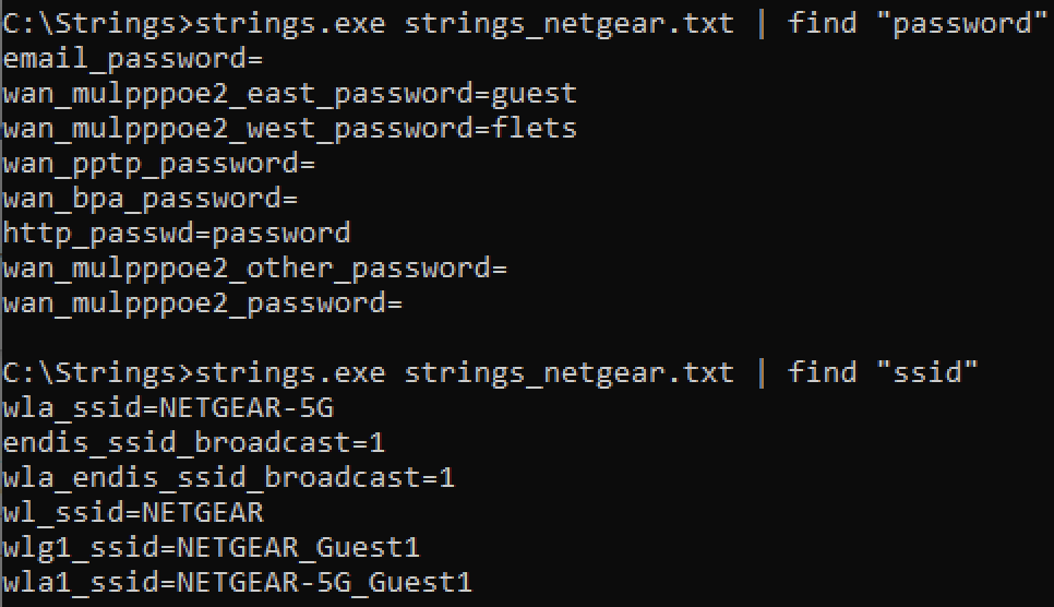
As you observe you can see that this particular router looks to have been reset before it was taken out of commission and sold since it has what looks like default values.
The best thing about the CH341a is that with other hardware, such as the Bus Pirate and Shikra I have found that I need to remove the SPI chip from the board to interact with it due to other circuits interfering with the targeted SPI chip. However, with the CH341a, I can just place a chip clip on the chip and dump the firmware without worrying about damaging the component by desoldering and soldering it on a breakaway board.
If you enjoyed this blog post and would like to get your hands dirty, come and join us at one of our Wild West Hackin’ Fest conferences. I will have this and many other labs available for attendees to play with.
Below are the links for the items that I purchased in the blog post.
- Amazon CH341a Pro with 1.8v add on: https://www.amazon.com/Organizer-EEPROM-CH341A-Adapter-Programmer/dp/B07V2M5MVH/ref=sr_1_1?keywords=ch341a&qid=1579295338&s=electronics&sr=1-1
- Amazon link for the 16 pin chip clip: https://www.amazon.com/WINGONEER-SOIC16-circuit-programming-adapter/dp/B01CYA9BTY/ref=pd_sbs_147_20?_encoding=UTF8&pd_rd_i=B01CYA9BTY&pd_rd_r=bcbc95e8-fcd8-4012-a17a-5e15d8a7da7b&pd_rd_w=4xhD3&pd_rd_wg=BUd6J&pf_rd_p=670e3530-913b-43e2-8005-da937e9a4fe8&pf_rd_r=AE4216TVMK66NZAYCY34&psc=1&refRID=AE4216TVMK66NZAYCY34
Ready to learn more?
Level up your skills with affordable classes from Antisyphon!
Available live/virtual and on-demand