Introducing LoRa (Long Range) Wireless Technology – Part 1
Ray Felch //
This write-up is the first of a multi-part series, providing an introduction to LoRa wireless technology and the LoRaWAN, low-power wide-area network (LPWAN). Interestingly, I came across this technology while researching a GPS tracking project that I was working on and quickly determined that this technology might be a viable alternative to using the GPS module. The deeper my research into LoRa went, I found the technology and the concept of sensor networks to be fascinating. From what I can tell from my initial research, LoRa appears to be a fairly new technology (less than 6 years) but is based upon CSS (chirp spread spectrum) and is similar to the spread spectrum (frequency hopping) techniques used in CDMA and other GSM protocols, which is not new at all.
The general outline of this part of the series will begin with an introduction to LoRa and LoRaWAN, highlighting the special use cases and including a working demonstration of a point-to-point (line of sight) communication between two REYAX LoRa modules. Continuing on, this series will proceed with introducing The Things Network (TTN) and how to build your own private LoRa Gateway for connecting to it. LoRaWAN comprises both a commercial and community facet. The Things Network is partnered with the LoRaAlliance and provides a community edition (free) access to the LoRaWAN. This series will finish up by demonstrating how to interface your own end node (sensor) devices (via your personal gateway) to TTN and its server-side applications.
General Information
With the increasing surge of IoT (Internet of Things) reaching billions of devices worldwide, the demands being placed on the community of wireless technology developers and maintainers have also increased significantly. Other wireless technologies such as WiFi, Bluetooth Classic, Bluetooth Low Energy, Zigbee, Zwave, etc., all play a significant role in providing support for the many use-cases of IoT devices currently in circulation. Each of these technologies can adequately address the specific needs of an IoT device, such as transferring high volumes of data, streaming video and audio, automation and monitoring, wearables (fitness and health), short-range communications, medical, automotive, and agriculture industries, and asset tracking, just to name a few.
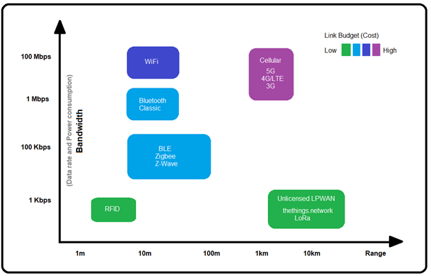
Although these various wireless technologies fill an important need in regard to providing robust features and functionality for our IoT devices, each has its own inherent limitations. Generally speaking, in terms of wireless communication, the limitations become obvious when comparing available bandwidth (data rate) versus desired range. For example, based on the diagram below, we can see that a Bluetooth Classic headset might have a maximum range of approximately 50m, with a data rate of just a few Mbps. This makes it ideal for delivering a reasonably sized payload of audio; however, the bandwidth would not be sufficient to support streaming video. Notice that WiFi and Cellular technologies support a much higher data rate (due to the higher bandwidth available) and can easily support streaming video and high internet traffic, but at a cost of high power (and in the case of WiFi, at an additional cost of signal range).
Link-Budget
The trade-offs between the various wireless technologies are often expressed in terms of ‘link-budget,’ which basically means the total cost to get a signal ‘linked’ from point-A to point-B (calculated in dBm). In reality, the formulas and calculations used by engineers to determine link-budgets are quite complex and take many things into consideration besides simply bandwidth versus range. Geographical locations, operating environment and buildings can obstruct and/or reflect RF (radio frequency) signals introducing loss in signal strength. Amplifier gain, antenna gain, impedance mismatches between cabling and antenna (resulting in high SWR), all have an effect on signal strength and receiver sensitivity. Ultimately, there are many factors that can affect the overall link-budget.
Referring to the same diagram, we see that LoRa has an extremely low link-budget (low cost to deliver signal), especially considering the higher distances (range) that it can achieve. This makes it an ideal choice for communicating with extremely low power IoT end devices where battery life is paramount. This is all made possible by keeping the data payloads as small as possible, which is typically the case with sensor-type endpoint devices.
Introducing LoRa
LoRa is a Low Power, Long Range wireless technology, focused on providing extremely low power (years on a single coin battery) and long range (10 miles line-of-site) solutions while working with IoT devices that typically generate very small data payloads (packets), such as humidity, temperature and moisture sensors, actuators, or water and gas meter monitoring.
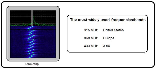
LoRa operates in the license-free ISM (Industrial, Scientific, and Medical purposed) sub-gigahertz band and is ideal for implementing low power, wide area (LPWAN) sensor networks.
LoRa is a proprietary low-power wide-area network modulation technique, developed by Cycleo of Grenoble, France and acquired by Semtech (founding member of the patented LoRaAlliance). It is based on spread-spectrum modulation techniques derived from chirp spread spectrum (CSS) technology. The allocated radio frequencies consist of EU 433 (433.05-434.79 MHz) and EU 863-870 (863-870/873 MHz) in Europe; AU915-928/AS923-1 (915-928 MHz) in Australia; US 902-928 (902-928 MHz) in North America; IN 865-867 (865-867 MHz) in India; AU 915-928/AS 923-1 and EU433 Southeast Asia.[4]; and 2.4GHz worldwide. Be careful to check that the transceiver frequency matches the band for your region when purchasing LoRa radio modules.
Introducing LoRa Alliance and LoRaWAN
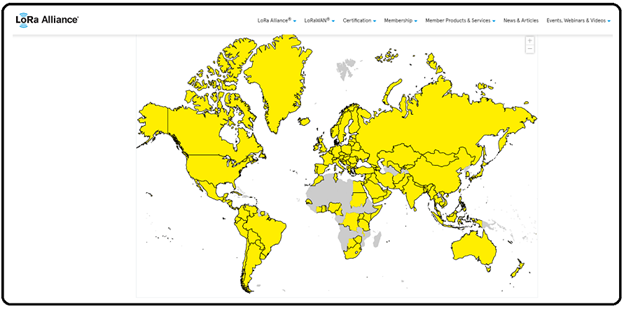
The LoRa Alliance is comprised of more than 500 members, including technology leaders like IBM, Cisco, and HP, as well as leading product companies such as Schneider, Bosch, Diehl, and Mueller. The goal of the alliance is to standardize a strong and growing ecosystem for the high-volume deployment of low power Internet of Things wide-area networks (LPWAN). Their ambitious goals entail being able to connect 50% of the predicted IoT volumes. They currently have 163 network operators in 177 countries.
According to the Alliance, “Network operators agree that they can only connect 10-15% of the predicted volume of IoT devices with classic (licensed bands) cellular technologies. WiFi and BT Smart serve some applications well, but clearly you are not going to connect moisture sensors for agriculture with WiFi. LPWA (low-power wide-area), with the inherent long range and low power characteristics will be the ‘go-to’ technology for IoT applications where remote locations, easy deployment, thousands of connections per gateway, and long battery life are required.“
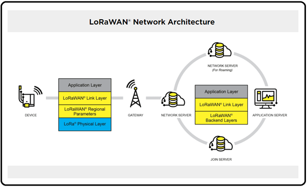
While LoRa defines the physical (radio) layer, the application and media access control (MAC) layers (LoRaWAN) specification is defined by the LoRa Alliance and acts as a networking layer protocol, which manages communications between its gateways and end nodes (IoT devices).
As stated by the LoRa Alliance, “The LoRaWAN® specification is a Low Power, Wide Area (LPWA) networking protocol designed to wirelessly connect battery operated ‘things’ to the internet in regional, national, or global networks, and targets key Internet of Things (IoT) requirements such as bi-directional communication, end-to-end security, mobility and localization services.“
OTA Duty Cycle
Note: The ‘over-the-air’ duty cycle of radio devices is often regulated by the government and is commonly set to 1%.
Likewise, the LoRaWAN specification dictates duty cycles for the join frequencies, the frequencies devices of all LoRaWAN-compliant networks use for over-the-air activations (OTAA) of devices. In most regions, this duty cycle is also set to 1%.
Additionally, The Things Network (community edition) has adopted a Fair Use Policy.
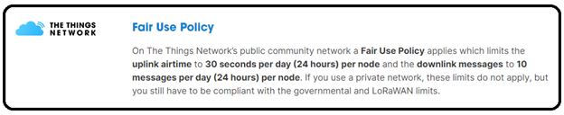
At first, these restrictions might seem to be a bit constraining, but in the use-case of low-power sensor node networks, this can work in our favor. Andreas Spiess described it best in his tutorial “LoRa / LoRaWAN De-Mystified” (see link at the end of this write-up).
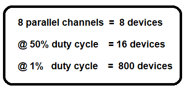
Based on the fact that our gateway concentrator has 8 RF channels, that means it can support up to 8 IoT devices in parallel. Realizing that 8 devices is small in comparison to the projected goals of hundreds of nodes per gateway, we could use these same 8 devices for 50% of the time and thereby increase our network of sensors by an additional 8 devices. Following that same concept, if we were to limit each device to operate for only 1% of the time, we can now support 800 nodes on our network on a single gateway, which, by the way, is also in compliance with the governing laws.
Security Keys:
LoRaWAN 1.0 specifies a few security keys: NwkSKey, AppSKey, and AppKey. All keys are 128 bits in length and using the AES-128 algorithm allows for the encrypting/decrypting of payloads, similar to the algorithm used in the 802.15.4 standard.
When joining a new endpoint device to the network, the device is first registered to an application (created by the account holder of the gateway). When a device is registered (joined), it is assigned an APPEUI, DEVEUI, and APPKEY all unique to the device. When activating the device for deployment on the network, the NwkSkey and AppSKey (session keys) are created using the mutually known AppKey.
The NwkSKey is shared with the network, and the AppSKey is kept private. As the name implies, the session keys are used for the duration of the current session and are regenerated on every subsequent over-the-air-activation (OTAA) session.
Note: Legacy versions of the LoRaWAN specification allowed for static activation of devices using Activation by Personalization (ABP). If ABP was used for activation, the same session keys are used for all sessions, unless manually changed by the account holder. Going forward with version 3.0 (The Things Stack), OTAA appears to be the preferred and more secure method of activation.
Network Session Key (NwkSKey)
Interaction between the endpoint (node) and the LoRaWAN server uses the NwkSKey to validate the integrity of each message with Message Integrity Code (MIC) in the same manner used in the 802.15.4 standard. The MIC (LoRaWAN uses AES-CMAC) prevents tampering with the message.
Application Session Key (AppSKey)
The AppSKey is used for the encryption and decryption of the payload. The payload is encrypted between the endpoint (node) and the Handler/Application Server protecting the messages sent and received from being read OTA.
Application Key (AppKey)
The AppKey is known only by the device and the application and, as stated above, is used for generating the two session keys.
Note: The Things Network (TTN) also allows us to use a default AppKey or customize our own.
Frame Counters
As with any wireless communication protocol, over-the-air captures of the radio signal is entirely possible, and with devices as cheap as $25. Fortunately for us, our data is encrypted using the AppSKey, and the network traffic is protected from tampering using the MIC (message integrity code) check. Frame Counter implementation was introduced in the 802.15 standard to help prevent replay attacks, where signals are captured and re-transmitted to spoof the original device.
When a device is activated, the frame counters (FCntUp) and (FCntDown) are set to zero. Simply put, when a message uplink occurs, the FCntUp is incremented and likewise, when a message downlink occurs the FCntDown is incremented. If either the device or network sees a frame counter less than the last seen frame counter, the entire message is dropped (ignored), thereby preventing MitM (man in the middle) attacks.
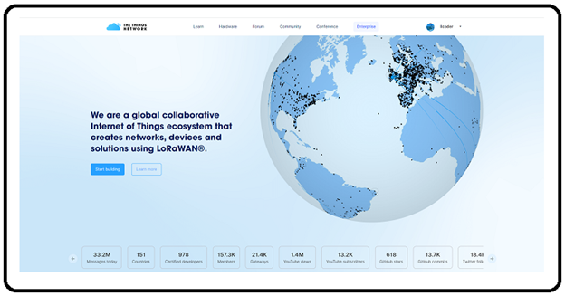
Introducing The Things Network

The Things Stack is version 3 of an enterprise-grade LoRaWAN network server, built on an open-source core. The Things Stack allows us to build and manage LoRaWAN networks on our own hardware, as well as in the cloud.
The Things Stack is deployed for a variety of commercial deployment scenarios; however, they also provide a Community Edition deployment, which offers a ‘free-to-use’ network server that provides the world’s largest community-based LoRaWAN network. To get connected with this free crowd-sourced, open, and decentralized LoRaWAN network, users need to sign-up for an account with TTN and either purchase or build their own gateway to connect to the network. I opted to build my own gateway using a Raspberry Pi-4 and RAK2243 Pi-HAT, and I will share this information later in the series.
The Things Network is based upon an open-source project that is dedicated to building a network for IoT devices based upon a protocol that allows these devices to connect to the internet without WiFi or cellular connectivity. The basic concept is centered upon endpoint (sensor) device transmissions being heard by a ‘within-range’ gateway, which then connects to the LPWAN.
Later in this series, I intend on providing a step-by-step guide to building your own personal LoRaWAN gateway for under $100 and demonstrate how to connect your DIY home-built (or store-bought) sensors to The Things Network using LoRaWAN via your gateway.
Simple LoRa Communication Demonstration
The following demonstration is based on an excellent example presented by akarsh98 of CETech (see link at the end of this write-up).
Hardware
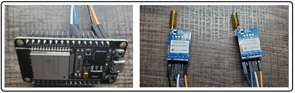
- (2) ESP32 microcontroller modules amazon.com/ESP-WROOM-32-Development-Microcontroller-Integrated-Compatible/dp/B08D5ZD528/
- (2) REYAX RYLR890 LoRa Radio Modules amazon.com/RYLR896-Module-SX1276-Antenna-Command/dp/B07NB3BK5H/
- Dupont jumper wires amazon.com/s?k=Jumper+Wire+Dupont&ref=nb_sb_noss_2
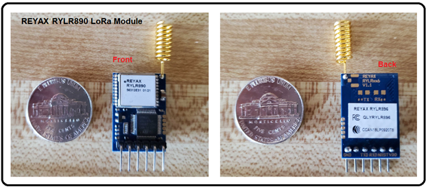
These radio modules can be interfaced using any micro-controller, as we will be using a standard UART (TX/RX) connection to communicate with the onboard STM32 microcontroller chip. Previously, I interfaced to the STM32 chip using an Arduino Uno development board and a small sketch, but for this demonstration, I will be using an ESP32 device. These are amazing inexpensive micro-controllers with built-in WiFi and Bluetooth compatibility out-of-the-box.
Note: Typically, sensor endpoints would not need the WiFi/Bluetooth capability of an ESP32 and would not be used in the wild, as those are high-power consumption features and defeat the intended goal of low power and long battery life. However, for the purpose of demonstrating LoRa wireless communication, the ESP32 provides us with a quick and simple setup (4 wires) and requires no soldering.
As stated earlier, our LoRa example is based upon a project by akarsh98 of CETech, which uses two ESP8266 (forerunner to the newer ESP32) and two REYAX RYLR890 LoRa Modules. Note, that I modified his code to support the newer ESP32 UARTS. The ESP32 has three hardware UARTs on-board, so the developers felt there was no longer a need to support the SoftwareSerial libraries used with the ESP8266.
The wiring is quite simple, Vcc and Gnd from the LoRa module goes to Vcc and Gnd on the ESP32 device. Tx from the LoRa module goes to GPIO-16 (RX2 pin) of the ESP32 and the Rx from the LoRa module goes to GPIO-17 (TX2 pin) of the ESP32.
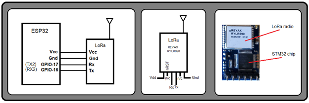
The fact that the LoRa module contains an on-board STM32 microcontroller, allows us to communicate to the LoRa radio module using a special set of AT commands. Our ESP32 device will communicate these commands directly to the STM32 over serial UART. The STM32 microcontroller, acting on our AT commands, will control the LoRa radio module for us. Later in the series, we will see how to control other LoRa radios directly, using our code and special open-source LoRa libraries.
LoRa Module AT Commands
As stated earlier, we will be sending special AT commands to control the LoRa radio. There are many AT commands available to us (link provided at the end of this write-up), but we will be using a few of the basic commands to get us up and running quickly. Generally, the AT commands fall into one of two groups: configuration and operational.
Configuration AT Commands
First, we need to configure the radio module:
- AT+MODE <sleep> (0 = Transmit and Receive mode (default), 1 = Places radio in sleep mode)
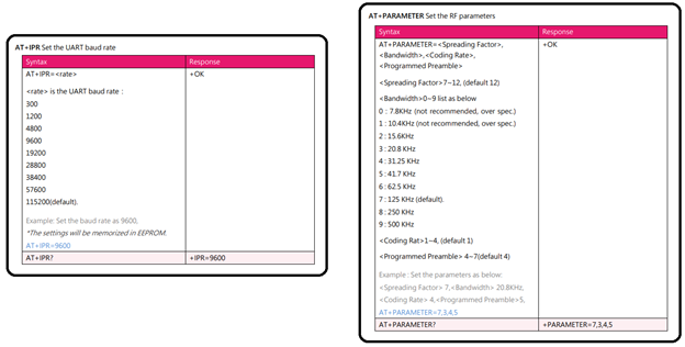
- AT+ IPR <set baud rate> (300 – 115200 [default is 115200])
- AT+ PARAMETER <Spreading Factor>, <Bandwidth>, <Coding Rate>, <Programmed Preamble> (see below)
- AT+BAND=<parameter> (868500000 = Europe, 915000000 = US [default is US])
- AT+ADDRESS=<address> (0 = 65535 [default is 0])
Spreading Factor: (7 – 12 ([default is 12])
Bandwidth: (0 – 9 [default is 7 = 125 kHz])
Coding Rate: (1 – 4 [default is 1])
Programmed Preamble: (4 – 7 [default is 4])
Spreading Factor and Bandwidth are two of the most important parameters with regard to LoRa low-power and range considerations. The higher the spreading factor, the greater the over-the-air (OTA) time, resulting in more power and better range, but at a cost of reduced data rate. This is where LoRa can be flexible with regard to configuring for range or for low-power operation. Admittedly, it took me a bit of time before I finally sorted this all out, so I’ll try and explain it with an example.
First, the data rate depends on the bandwidth used and spreading factor. LoRaWAN can use channels with a bandwidth of either 125 kHz, 250 kHz, or 500 kHz (depending on the region or the frequency plan). The spreading factor is chosen (and set) by the end device (sensor) and influences the time it takes to transmit a frame.
Increasing the bandwidth or decreasing the spreading factor allow the bytes to be sent in a shorter period of time. The general rule is, doubling the bandwidth allows us to send twice the data payload in the same amount of time. Likewise, decreasing the spreading factor by one also allows us to send twice the data payload in the same amount of time.
Keep in mind that lowering the spreading factor can also make it more difficult for the gateway to receive the transmitted signal, due to it being more susceptible to noise. If the gateway is a great distance away, you might use a higher spreading factor (SF10) (data rate will be slower, but more reliable). If the gateway is in close proximity, we can afford to use a lower spreading factor (SF7) and increase our data rate. Obviously, keeping our data payloads as small as possible contributes to overall data rate, range, and power consumption.
Operational AT Commands
After configuring the radio, we are ready to begin transmitting and receiving, which can be accomplished with the following commands:
Note: The address of each LoRa Module (Transmitter and Receiver) must be identical in order to communicate with each other.
Transmitting
AT+SEND=<Address>, <Payload Length>,<Data> (Address = 0 – 65535, Payload Length = Max 240 bytes, Data = ASCII format)
Receiving
+RCV =<Address>, <Payload Length>,<Data>,<RSSI>,<SNR> (same as SEND with two additional parameters)
- RSSI (Received Signal Strength Indicator) is Received Signal Strength Indicator measured in dB and SNR is the Signal-to-Noise-Ratio measured in dB
Note: ‘AT’ is not required for Receiving, because we are simply receiving data (not actually issuing a radio command).
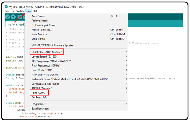
Upload the code (assumes Arduino IDE is installed and operational)
- Connect an ESP32 to a USB port on the PC
- Enter the Arduino IDE and under tools, select ESP32 Dev Module board and USB port
- Upload the code (sketch) to the ESP32
Disconnect the ESP32 and connect the second ESP32. Follow the same steps for the second ESP32.
LoRa Radio Messenger sketch (copy and paste as a new sketch for both ESP32 devices)
/* LoRa transmitter - receiver messenger -- llcoder 11-18-2021
* There are three serial ports on the ESP known as U0UXD, U1UXD and U2UXD.
*
* U0UXD is used to communicate with the ESP32 for programming and during reset/boot.
* U1UXD is unused and can be used for your projects. Some boards use this port for SPI Flash access though
* U2UXD is unused and can be used for your projects.
*/


#define RXD2 16   // LoRa TX (ESP32 RX2)
#define TXD2 17   // LoRa RX (ESP32 TX2)


#include<LoRa.h>


String incomingString;
String PrStr;                                           // String used to print the incoming string after decoding it


void setup() {
  Serial.begin(115200);
  Serial2.begin(115200, SERIAL_8N1, RXD2, TXD2);  // (ESP32 UART)
}


void loop() {
  if (Serial.available()){
        incomingString = Serial.readString();
          if(incomingString.length()>2){
          Serial.print("YOU: ");
          Serial.println(incomingString);
          String messStr = "AT+SEND=0,";              // messStr(AT COMMAND) is to be sent to the LoRa module to send the relevant data
          messStr += (incomingString.length()-2);
          messStr += ",";
          messStr += incomingString;
          Serial2.print(messStr);
          }
    }


   else if (Serial2.available()){                  // this will read the incoming data from the lora and decode it and print it on serial monitor
        incomingString = Serial2.readString();
        String recTest = incomingString.substring(1,4);
        if(recTest == "RCV"){
        String messagesize;
        int addr_start = incomingString.indexOf(',');
        int addr_mid = incomingString.indexOf(',', addr_start + 1);
        messagesize = incomingString.substring(addr_start + 1, addr_mid);
        PrStr = incomingString.substring(addr_mid + 1, (addr_mid + 1 + messagesize.toInt()));
        Serial.print("THEM: ");
        Serial.println(PrStr);
        }
    }
}
Sample Output
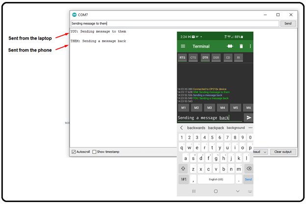
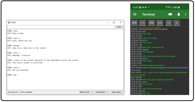
Both ESP32 devices have been programmed with the same code and are capable of transmitting as well as receiving. For this demonstration, one ESP32 is connected to a laptop via USB, and the second ESP32 is connected to a mobile phone via OTG-USB. Serial terminals have been opened on both devices and are in receive mode, monitoring for LoRa radio signals. If the signal received does not specify the correct address in its header, the message is dropped (ignored). Otherwise, it is accepted and displayed in both terminals.
The following screenshot shows a typical back and forth message sequence:
Test Results
Testing was done to determine the approximate range for reliable two-way communication. In my location (urban area with buildings, trees, and hills), the line-of-site is somewhat limited. With myself stationed at the laptop (indoors), a family member completed a trek outside with the phone and we both closely monitored our two-way communication.
Based upon this preliminary run, I determined the range to be approximately 150 meters. Obviously, with one of the radios being indoors where the signal is obstructed by the structure, it is likely that this contributed to a significantly reduced range. For this reason, we conducted another test on an urban stretch of road, line-of-site and less obstructed by buildings, trees, or hills. In this case, we found that our range had increased, to approximately 700 meters (0.5 miles), but still well below the 13km claimed by Semtech and others.
Taking into account that our radio modules are presently attached to the microcontroller using push-on cabling, rather than soldered, and are being powered via USB OTG adapters, rather than dedicated power banks, a more definitive test may be in order, preferably conducted in a more rural and less populated area.
Summary:
Although LoRa wireless and LoraWAN appear to be tightly coupled to a specific use-case of IoT technology (extremely small data payload devices, sensors, activators, etc.), there is an obvious need for this new wireless technology, if for no other reason than to off-load the already heavily taxed traffic of existing Bluetooth and Wifi IoT devices.
More so, in an agricultural environment, where the range of coverage could be in the order of miles, Bluetooth and WiFi fall seriously short. Likewise, with a deployment of hundreds (if not thousands) of sensors to a wide area, battery maintenance becomes an important concern and battery changes need to be held to a minimum.
With LoRa wireless technology, sensors have been verified to last years on a single button cell battery, and under ideal rural conditions reach line-of-site ranges of 13km (10 miles) or ideal urban conditions of 5km (3 miles). As a side note, researchers have proposed that LoRaWAN could solve some of the issues regarding the power demands of 4G/5G technologies.
LoRa Wiki states that chirp spread spectrum may also be used in the future for military applications, as it is very difficult to detect and intercept when operating at low power. Fun fact: CHIRP of (CSS) is yet another acronym that stands for Compressed High Intensity Radar Pulse.
At the time of this writing, LoRa and LoRaWAN are still in their infant stage (approximately 5 years old) but are rapidly gaining momentum. Personally, I am pretty amazed with the entire concept of IoT Low-Power Wide Area Networks, and how the community is quickly adopting and getting involved with this new wireless technology. So much so that I have recently built my own personal LoRa gateway which is connected to The Things Network, and I am currently developing experimental sensor nodes that send humidity and temperature payloads to the LPWAN. Part Two of this series, I will go on to describe how to build your own personal LoRa Gateway for under $100 using a Raspberry-Pi and RAK2243 Pi-HAT, and how to connect it to The Network of Things. Additionally, this series would not be complete if I did not demonstrate how to create an application and register/activate a sensor node to the application. Once activated, we will be able to connect to the TTN web-based console and watch the live data as it is received via the gateway. Stay tuned.
Informative Links:
https://lora-developers.semtech.com/documentation/tech-papers-and-guides/lora-and-lorawan/ Semtech: DEVELOPER PORTAL
https://www.youtube.com/watch?v=hMOwbNUpDQA Andreas Spiess: #112 LoRa / LoRaWAN De-Mystified / Tutorial
https://www.youtube.com/watch?v=jnvik7sUosw CETech: LoRa based messenger Project| LoRaWAN | LoRa Basic Project
https://play.google.com/store/apps/details?id=de.kai_morich.serial_usb_terminal&hl=en_IN USB Serial Terminal (Mobile app)
https://www.thethingsnetwork.org/ TTN The Things Network
https://www.thethingsnetwork.org/docs/lorawan/security/ LoRaWAN Security Keys
https://www.youtube.com/watch?v=dxYY097QNs0 Excellent video explaining the LoRa chirp
https://www.youtube.com/watch?v=NoquBA7IMNc Matt Knight, Bastille Networks: Decoding the LoRa PHY (33c3)
http://reyax.com/wp-content/uploads/2020/01/Lora-AT-Command-RYLR40x_RYLR89x_EN.pdf LoRa Module AT commands document
Ready to learn more?
Level up your skills with affordable classes from Antisyphon!
Available live/virtual and on-demand