Understanding Zigbee and Wireless Mesh Networking
Ray Felch //
Preface:
Recently, I acquired a few home automation devices, so that I might research Zigbee and get a better understanding of how this very popular wireless technology interconnects with the internet of things (IoT’s) and to determine just how secure this platform really is. I was already somewhat familiar with home automation in regard to using the Bluetooth Low Energy (BLE) Mesh topology. However, major advances have been made with IoT devices, including but not limited to: connecting very low power devices (in many cases battery-powered and lasting for years), low data rates (20-250Kbits/sec) providing for more reliable communications, and self-forming and self-healing networks that grow as your needs grow.
The following document outlines my research of the Zigbee protocol and its mesh topology as it applies to small and large-scale automation. Hopefully, others might benefit from the information that I discovered along the way.
Useful Hardware
Preliminary preparation for my research into the Zigbee protocol consisted of getting familiar with some of the existing hardware available for analyzing and interacting with the Zigbee network. It didn’t take long to find out that a very popular Zigbee sniffer was the RZRaven USB Sniffer which came with RiverLoop Security’s Killerbee framework (https://github.com/riverloopsec/killerbee) pre-installed (selling for around $100). Unfortunately, after exhaustive searching, I discovered that the RZRaven has been discontinued and is nowhere to be found.
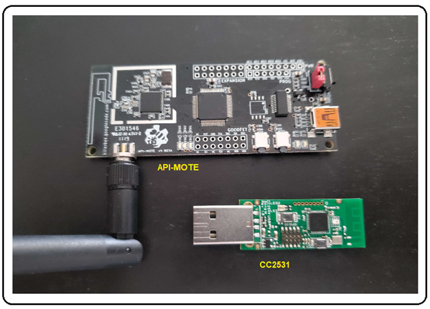
Reaching out to the community, I learned that another dongle existed known as the ApiMote, and it also came pre-installed with the Killerbee framework. I also found out that it was available through the Attify Store (https://www.attify-store.com/products/apimote-for-zigbee-sniffing-and-transmission) for $149. This transceiver dongle is also capable of packet injection!
Other Zigbee sniffers considered were Nordic’s nRF52840 (https://www.mouser.com/new/nordic-semiconductor/nordic-nrf52840-usb-dongle) and the Texas Instruments CC2531 (http://www.ti.com/tool/PACKET-SNIFFER). The TI CC2531 option also comes with an impressive GUI software application for dissecting and displaying the captured packets.
I decided to go with the Api-Mote/Killerbee dongle, as well as the very inexpensive Texas Instruments CC2531 USB dongle (cost under $10).
Why Zigbee?
Some may ask: “Why Zigbee? We already have Wi-Fi and Bluetooth short-range communication standards that provide greater range and support higher data rates.” While it is true that greater range and higher data rates allow for superb streaming video using Wi-Fi (and to a lesser degree, audio streaming using Bluetooth), the requirements for (Zigbee) control and sensor networks are far less demanding. Technically speaking, that is exactly why Zigbee is the better choice, as control and sensor network nodes are typically less than a few meters apart from each other, so range is hardly an issue. And communication between nodes can be established using very small packet sizes, thereby allowing very low data rates (20-250 kbps). Lower data rates and close proximity nodes yield more reliable communications (fewer retries, etc.) and work well with low power, battery-operated end-point devices, keeping costs down dramatically as the network continues to grow in size.
Background Information
Zigbee is an open standard wireless technology designed to facilitate low-cost, low-power wireless internet of things (IoT) networks.
Specifically, Zigbee is a low-cost, low-power, self-forming, self-healing wireless mesh network standard solution, aimed at providing wireless control and monitoring applications with an emphasis on supporting battery-powered, low data rate devices. This protocol is typically used in home automation (HA) and commercial building automation, industrial control systems, and the medical/health care industries.
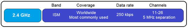
Zigbee integrated circuits (IC’s) encompass microcontrollers and radios operating in the unlicensed ISM (industrial, scientific and medical) bands: 2.4GHz for the majority of areas worldwide. There are a few devices using sub-GHz (745MHz in China, 878MHz in Europe, and 915MHz in the United States and Australia), but this is generally the exception to the rule. Zigbee uses 16 channels (11-26), 2 MHz wide with 5 MHz separation in the 2.4GHz ISM band. It should be noted that when a Zigbee network is first formed, the coordinator (hub) will scan the available channels and select the best channel to operate on (least RF interference), and only that one channel will be used going forward (no channel hopping).
Zigbee is an IEEE 802.15.4-based, wireless networking standard, which is basically used for two-way communication between sensors and control systems. Zigbee is a short-range wireless communication standard like Bluetooth and Wi-Fi while covering a range of 10 to 100 meters.
By creating a network of devices that can communicate with each other (in a mesh network), the 10 to 100-meter range can be extended significantly, making it extremely useful in commercial lighting and industrial control automation applications. New devices (nodes) can easily join the network (with a theoretical maximum limit of 65,000 nodes). Rerouting of communication traffic (due to failed nodes) provides a form of self-healing for the network.
Zigbee endpoint devices (lights, plugs, sensors, switches, thermostats, etc.) are extremely low-power and can last years on tiny batteries. Also, the fact that Zigbee is based on an open standard assures consumers and developers that devices will interoperate.
Brief History
Zigbee has been around for a long time, initially conceived in the 1990s. The IEEE 802.15.4-2003 specification was ratified in 2004 and was made available the following year, known as the Zigbee 2004 Specification. In 2006, an upgraded specification was introduced as Zigbee 2006 Specification, replacing the ‘key-value’ pair structure of the 2004 stack with the Zigbee Cluster Library (ZCL). This library is composed of standardized commands and attributes organized under groups (clusters) with such names as Smart Energy, Home Automation, Zigbee Light Link, etc.
In 2007, Zigbee Pro was introduced, always maintaining backwards compatibility with the Zigbee legacy networks. Zigbee Pro devices can join legacy networks and legacy devices can join Zigbee Pro networks. However, routing options differed which resulted in a condition that Zigbee Pro devices must become non-routing Zigbee end devices (ZEDs) when on a legacy network, and legacy Zigbee devices must become ZEDs on a Zigbee Pro network.
According to the German computer e-magazine, Heise Online, Zigbee Home Automation 1.2 (2013) is using fallback keys for encryption negotiation which are known and cannot be changed. This makes the encryption on many legacy devices highly vulnerable. Fun fact: Back then, the well-known default global trust center link key defined by the ZigBee Alliance, had a default value of 5A 69 67 42 65 65 41 6C 6C 69 61 6E 63 65 30 39 (ZigBeeAlliance09) and was used or supported by the device if no other link key is specified by the application at the time of joining. Note: Zigbee 3.0 (going forward) silently ignores the request to join the network if a device attempts to authenticate using the well-known ‘ZigBeeAlliance09’ trust center link key.
Zigbee Development Platforms
EmberZNet is the implementation of Zigbee by Silicon Labs. It consists of the core Zigbee stack, Zigbee Cluster Library support, and an Application Framework. With the aid of AppBuilder in Simplicity Studio, developers can easily create a Zigbee application that can be run on one of Silicon Labs’ development kits.
Z-Stack is a component of the SimpleLink™ CC13x2 / CC26x2 Software Development Kit. This component enables development of Zigbee® 3.0 specification-based products. Z-Stack is TI’s complete solution for developing certified Zigbee 3.0 solutions on CC13x2 and CC26x2 platforms.
Zigbee Alliance
The Zigbee Alliance board of directors is comprised of executives from Amazon, Apple, Comcast, Google, IKEA, The Kroger Co., LEEDARSON, Legrand, Lutron Electronics, MMB Networks, NXP Semiconductors, Resideo, Schneider Electric, Signify (formerly Philips Lighting), Silicon Labs, SmartThings, Somfy, Texas Instruments, and Wulian.
Established in 2002, the Zigbee Alliance is a group of more than 500 companies that maintain and publish the Zigbee standard. The organization publishes application profiles that allow multiple OEM vendors to create interoperable products. The relationship between IEEE 802.15.4 and Zigbee is similar to that between IEEE 802.11 and the Wi-Fi Alliance.
As of May 11, 2021, the Zigbee Alliance has been rebranded to Connectivity Standards Alliance (CSA).
TECHNICAL INFORMATION
Zigbee Devices Types:
- Zigbee Coordinator (ZC)
- Zigbee Router (ZR)
- Zigbee Endpoint Device (ZED)
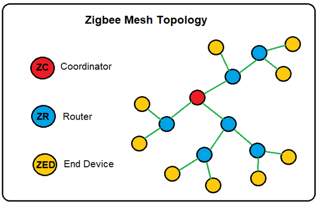
The Zigbee network has exactly one Zigbee Coordinator (ZC), responsible for forming and coordinating the network. Forming includes choosing the PAN ID (personal area network identification) to identify the network and determining the physical radio channel to operate on. The coordinator is also responsible for configuring and authenticating routers and end devices that join the network. The coordinator is the Trust Center and stores all critical information about the Zigbee network, including encryption keys and link keys.
The Zigbee Router (ZR) represents intermediate nodes to assist in the relaying of data between nodes in the network. They are instrumental in the building of the Zigbee network where packets are exchanged. The Zigbee routers enhance the mesh network by increasing the range of the network (relaying packets throughout the mesh network), increasing the reliability of the packets being exchanged, and providing a means for additional nodes to join the network (with the help of the coordinator). A good example of Zigbee Router might be a smart plug (powered by a wall outlet). This device has an endless supply of main power and is, therefore, always on. The fact that this smart plug is a full-function device (FFD) makes it ideal for routing traffic and a strong candidate for becoming a parent to reduced functioning (RFD) endpoint devices.
The Zigbee Endpoint Device (ZED) are nodes that are logically attached to a Zigbee Router (ZR), and are typically devices such as lights, plugs, sensors, switches, thermostats, etc., and communicate only with the Zigbee Router (parent) that they are related to. ZED’s are often battery-powered devices and sleep most of the time. They cannot communicate with other Zigbee Endpoint Devices (ZEDs) directly. In this sense, ZED’s are considered Reduced Function Devices (RFD’s).
ZED’s have lower power requirements (due to active sleep mode) and can achieve long lifetimes on batteries. In contrast, ZR’s and ZC’s (which are always awake) have high power requirements and for this reason, cannot be battery powered.
ZED’s are typically off (sleep mode) most of the time, thus not able to receive any traffic sent to them in real-time. Periodically, they wake up and check for messages by querying their (parent) router (ZR) that they are logically connected to. Note: The router buffers the data intended for the ZED (child) and sends that data only when polled by the ZED on wake up. Wake-up times are defined by the application developer, NOT the Zigbee specification.
ZED’s can immediately communicate with their (parent) router on wake up because ZR’s are always awake.
Zigbee Stack
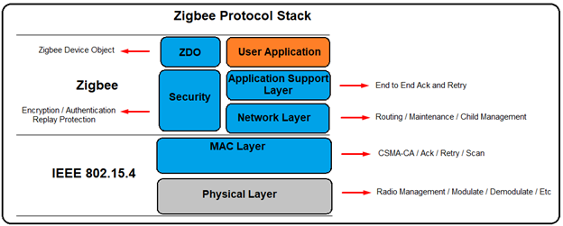
PHYSICAL Layer
The Physical layer includes the interface of the physical radio and MAC layer, radio on/off control, modulation and demodulation, channel selection, link quality estimation, and energy detection. Zigbee radios share the 2.4 GHz ISM band with Wi-Fi and, using 16 channels (11-26), 2 MHz wide with 5 MHz carrier separation between channels.
MAC Layer
In the MAC header, there is a 2-byte field “Frame Control.” Bit 0-2 indicating the frame type. Typically, there are four frame types:
- Beacon, used to scan networks
- Data, used to transmit data from higher layers
- ACK, acknowledgement
- MAC Command, control commands of MAC layer, like MAC association procedure.
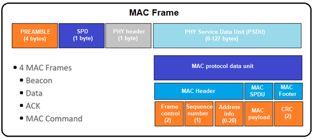
At the end of each MAC frame, there are two bytes CRC used to verify the integrity of the packet.
NETWORK Layer
The Network layer is located between the MAC layer and the application support sub-layer (APS) and is where the network management takes place. The Network layer takes care of the network structure, routing, and security.
Device Types
IEEE-802.15.4 defines two network device types:
- FFD, Full Functional Device, capable of performing all the duties described in the IEEE 802.15.4 standard and can accept any role in the network.
- RFD, Reduced Functional Device (generally battery-powered), has limited capabilities.
Note: The processing power and memory size of RFD devices are normally less than those of FFD devices.
In Zigbee, there are three physical device types:
- Coordinator (forms the network, has routing capability, is powered by main, must always stay awake, can be a parent)
- There can only be one coordinator per network. Coordinators node ID is always 0000.
- Router (cannot form the network, has routing capability, is powered by main, must always stay awake, can be a parent)
- End Device (cannot form the network, does not have routing capability, is powered by main or battery, must have a parent)
- End device can be non-sleep end device or sleep end device.
Network Address
Zigbee uses PAN ID and extended PAN ID to identify a network.
- PAN ID is a 16-bit identifier that all nodes in the PAN (Personal Area Network) will share. The PAN ID is chosen by the coordinator upon forming the network and is used to distinguish it from other nearby networks that may happen to be on the same channel.
- Extended PAN ID is a fallback network identifier known by all nodes in the PAN. The normal (short) PAN ID is transmitted in ‘over the air’ packets as it is quicker to send 16 bits versus 64 bits. The extended PAN ID is also unique for every PAN and is chosen by the coordinator upon forming the network. However, the extended PAN ID is seldom transmitted over the air and is used more as a backup criteria in case PAN ID conflicts were to arise. Using the extended PAN ID would allow the coordinator to talk to all nodes and establish a new PAN ID to move to and resolve the issue. The extended PAN ID is only sent over the air in response to an “active scan” (new nodes requesting to join the network) and when a rare PAN ID update is occurring.
Device (Node) Address
Like the Network address, each node in the network has a unique short and long address to distinguish it from the other nodes in the network.
- The long address is the 64-bit IEEE assigned MAC address (EUI-64) and is a globally unique ID (GUID) that is generally assigned during the manufacturing stage. Being a globally unique ID means that no two IEEE radios in the world will have the same GUID. As is the case with the extended Network address, the long (EUI-64) address is seldom sent over the air, except for join (Beacon) requests and/or to resolve rare node address conflicts.
- The short address (16-bit), assigned by the coordinator when the node joins the network, is used over the air. Known as the Node ID, this address is unique to its home PAN network.
APPLICATION Layer
The ZigBee Application layer is called application framework (AF) and runs on top of the Application support layer (APS). The AF supports many applications and processes incoming data between registered applications. Some registered applications are defined within the Zigbee specification, while others are vendor implementations. Zigbee defines an application as a profile. ZigBee profiles are identified with an integer between 0 and 240, called an endpoint. There are two types of application profiles: public and vendor-specific. A special profile with an endpoint ID of zero is the ZDO (Zigbee device object) and it is used for network configuration and setup.
The Zigbee Alliance has defined a few profiles, such as Smart Energy, Home Automation, Commercial Building Automation, Toys, etc.
Device endpoints versus Logical endpoints
A logical endpoint ID is an 8-bit value, ranging from 0 to 255.
- Endpoint 0 is reserved for Zigbee Device Object (ZDO), used for network management purposes.
- Endpoint 1 to 239 can be used by user applications.
- Endpoint 240 to 254 are reserved for special applications.
- Endpoint 255 is used for broadcasting.
Broadcast Addresses
Applications register with an endpoint identifier at the AF layer. When the AF layer processes an incoming message, it is passed on to the appropriate cluster for handling based on the endpoint identifier. If a packet arrives for an endpoint identifier that is not registered, the packet is silently dropped.
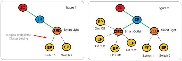
Endpoints are logical extensions defined in the application layer that can be thought of as devices accessible through a single ZigBee radio node. For example, a light switch attached to a radio node might be one endpoint (physical), and a dimmer attached to the same node might be another endpoint (logical) rather than a completely new application (see figure 1). In another example, a smart outlet strip attached to a radio node might be an endpoint (physical), and each outlet on the strip attached to the same node might be other endpoints (see figure 2).
CLUSTERS
Zigbee clusters are based on a client/server model and are used to implement an application protocol between two or more devices. Clusters are a group of commands and attributes that define what a device can do (a group of actions by function). Each cluster is assigned a cluster ID which is defined in the Zigbee Cluster Library (ZCL). A cluster may be defined with several attributes and commands.
A cluster in the ZigBee Cluster Library is an object, containing both methods (commands) and data (attributes).
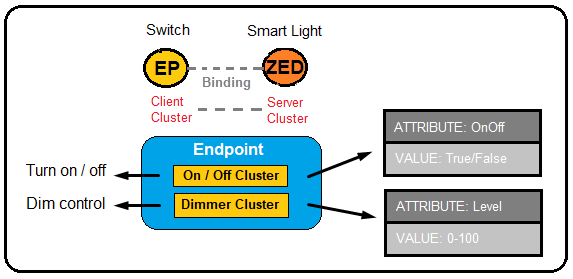
Binding is an action in ZigBee which defines relations between two devices, specific endpoints, and cluster ID. It provides a mechanism for attaching an endpoint on one node to one or more endpoints on another node and can even be applied to groups of nodes.
SECURITY
Security within the Zigbee network is based on a network key and link keys. Unicast communication between any two application layer devices is secured using a 128-bit link key shared by the two devices, while broadcast communications are secured by a 128-bit network key shared among ALL devices in the network. The intended recipient(s) of the communication is always aware of the precise security arrangement; by that, the recipient knows whether the frame is protected with a link key or a network key.
NETWORK Key
Zigbee network security uses a network-wide key for encryption and decryption. The network key is a 128-bit key shared by all devices in the network. Normally, it’s randomly generated by the coordinator when the network is formed. When new devices join the network, they must get a copy of the network key.
TRUST CENTER Networks
In a Zigbee network, the role of who distributes a network key to new devices is called the trust center (TC). There are two security models, centralized security network and distributed security network.
In a centralized security network, there is only one trust center, and it’s the coordinator. All new devices will get the network key from the coordinator.
In a distributed security network (no coordinator device), each router is a trust center. New devices can get the network key from any router, as any router can authorize and authenticate new devices that wish to join.
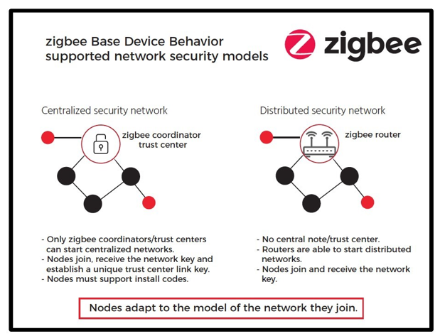
Note: The decision to use a Distributed Trust Center Network or a Trust Center Network is done at the time the network is formed. There is no way to change this decision after the network has been started.
All devices that are authorized to join the network have a copy of the key and use it to encrypt and decrypt all network messages. The network key also has a sequence number associated with it to identify a particular instance of the key. Occasionally, when the network key is updated, the sequence number is incremented to allow devices to identify which instance of the network key has been used to secure the packet data. The sequence number ranges from 0 to 255. When the sequence number reaches 255, it wraps back to 0. All devices that are part of a secured Zigbee network have a copy of the network key.
As the network key needs to be transported from one device to another, the key value needs to be encrypted during transport. This encryption is done in the application layer.
NETWORK Layer Security
Packet Security
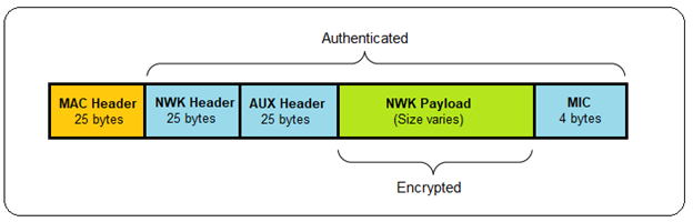
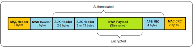
A packet secured at the network layer is composed of the following elements (see below).
Auxiliary Security Header
The auxiliary header contains data about the security of the packet that a receiving node uses to correctly authenticate and decrypt the packet. This data includes the type of key used, the sequence number (if it is the network key), the IEEE (long) address of the device that secured the data, and the frame counter.
Authentication and Encryption
Zigbee uses a 128-bit symmetric key to encrypt all transmissions at the network layer. The network and auxiliary headers are sent in the clear but authenticated, while the network payload is authenticated and encrypted. AES-128 is used to create a hash of the entire network portion of the message (security header and payload), which is appended to the end of the message.
This hash is known as the Message Integrity Code (MIC) and is used to authenticate the message by ensuring it has not been modified. A receiving device hashes the message and verifies the calculated MIC against the value appended to the message. Alterations to the message invalidate the MIC and the receiving node will silently discard the message. Note: Zigbee presently uses a 4-byte MIC.
Message Integrity Code (MIC)
The nonce (see figure 3) used in the AES-CCM* encryption process is a 13-octet string constructed using the security control field, the frame counter, and the source address fields of the Zigbee security header. The size of the MIC can be 32 bits, 64 bits, or 128 bits (32 bits in the following example).
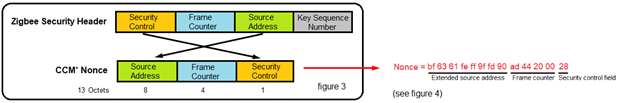
The following screenshot (see figure 4) shows the Zigbee Network Layer and Zigbee Security Header sections of a Broadcast packet sent by my Smart Plug #1:
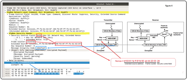
Network Security Frame Counter
A frame counter is included in the auxiliary headers as a means of protecting against replay attacks. All devices have their own unique outgoing frame counter and they maintain a list of their neighbors’ and children’s frame counters. Every time a device sends a packet, it increments its outgoing frame counter. All normal network communication is required to have network security and a valid frame counter. The only exception is during joining when devices do not yet have the network key. In that case, a joining device’s messages are relayed through its parent until it is fully joined and authenticated. Any other messages that are received without network layer security are silently discarded.
A receiving device verifies that the frame counter of the sending device has increased from the last value that it saw. If it has not increased, the packet is silently discarded. If the receiving device is not the final destination, the packet is decrypted and modified to include the routing device’s frame counter. The packet is then re-encrypted and sent along to the next hop (known as hop-by-hop security).
The frame counter is 32 bits and may not wrap to zero. The network key can be updated before the frame counter reaches its maximum value. When that occurs, the frame counter may be reset to zero if the local device’s value is above 0x80000000.
APPLICATION SUPPORT LAYER (APS) SECURITY
End-to-End Security
APS security is intended to provide a way to send messages securely within a Zigbee network such that no other device can decrypt the data except the source and destination. This is different from network security, which provides only hop-by-hop security. In that case, every device that is part of the network hears the packet being sent to its destination and decrypts it.
APS security uses a shared key (link key) that only the source and destination know about, thus providing end-to-end security. Both APS layer and network layer encryption can be used simultaneously to encrypt the contents of a message. In that case, the APS layer security is applied first, and then the network layer security.
A packet secured at the APS layer is composed of the following elements (see below):
LINK Keys
APS security uses a peer-to-peer key known as the link key. Both devices must have already established this key with one another before sending APS-secured data. There are two types of link keys: trust center link keys and application link keys.
Trust Center Link Keys
The trust center link key is a special link key in which one of the partner devices is the trust center. The stack uses this key to send and receive APS command messages to and from the trust center. The application may also use this key to send APS-encrypted data messages. All devices in a Zigbee network must have link keys. In a Trust Center Network, the devices must have a Trust Center Link Key. In a Distributed Trust Center Network, this key is called a Distributed Trust Center Link Key.
Application Link Keys
Application link keys are shared keys that may be established between any two nodes in the network, where neither device is a trust center. They may be used to add additional security to messages being sent to or from the application running on a node. Devices can have a different application link key for each device with which they communicate.
A device may preconfigure an application link key or request a link key between itself and another device. In the latter case, it issues a request to the trust center encrypted with its trust center link key. The trust center acts as a trusted third party to both devices, so they can securely establish communications with one another.
Unencrypted APS Data
APS layer security operates independently of network layer security. It is required for certain security messages (APS commands) sent to and from the trust center by the Zigbee stack. Unlike network security, APS security for application messages is optional.
Install Codes
An installation code key is just a preconfigured trust center link key used to enter the Zigbee network and obtain the current network key. Because this unique key must be known to both the joining device and the trust center at the time of network entry, a piece of shareable data known as the “install code” is used to derive the key at both sides. As part of this process, the installation code and the joining device’s EUI64 must be conveyed out-of-band to the network’s trust center to allow the proper link key table entry to be created.
The code can be any arbitrary value of 6, 8, 12, or 16-bytes, followed by a 16-bit CRC (least significant byte first) over those bytes. This code is then used as the input to a Matyas-Meyer-Oseas (MMO) hash function with a digest size (hash length) equal to 128 bits. The 128-bit result of this AES-MMO hash function is used as the value for the preconfigured trust center link key for that device. The trust center can then install a key table entry with that key and the EUI64 of the joining device, which then allows the authentication to take place successfully during joining, and the joining device can successfully receive and decrypt the network key.
It should be noted that, as of Zigbee 3.0, all certified devices are required to have install codes, but use in the network is ultimately decided by the trust center.
ZIGBEE PACKET SNIFFING
Joining a Network
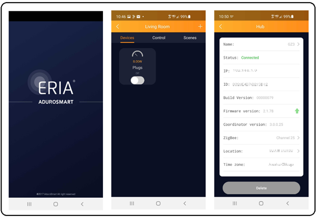
The following Wireshark captured packets will demonstrate the process of how a new device joins a network. For this example, I created a Zigbee network using a coordinator (AduroSmart ERIA Smart Home Hub / Gateway) and a router device (Innr Zigbee Smart Plug).
Association Request
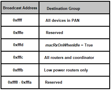
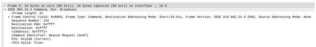
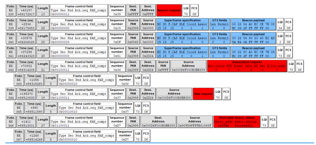
The process of joining a network begins with the joining device sending a Beacon request command on all channels. Basically, the new device is asking, “Is anybody out there?” In the following frame (5), notice that the destination for this Beacon request is 0xffff, which we discovered earlier in this write-up to be a broadcast to all nodes in the area.
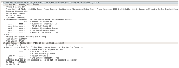
In response to Beacon requests, all Zigbee routers and coordinators in the area will respond with a Beacon response. Each router and coordinator on the channel will announce, “Here I am!” The Beacon response frame contains useful information about the responding node and the network it belongs to.
In the following frame (14), we can see the network PAN ID is 0x2999 and the source of this Beacon response is 0x0000, meaning this device is the coordinator for the Zigbee network PAN 0x2999. The Superframe Specification field verifies this as well, PAN Coordinator = True. Also notice that the Association Permit = True, meaning the coordinator is giving the joining device permission to join (be associated with this network).
Additionally, note that the Frame Control Field for beacons is 0x8000 and the Stack Profile, in this case, is 0x02 (Zigbee Pro).
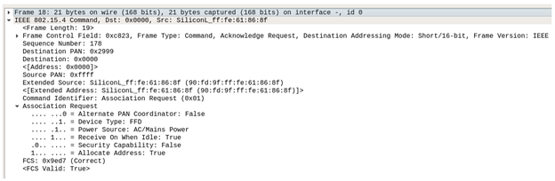
Now that a ‘permission to join’ has been granted, the next step is for the joining device to send an Association Request to the coordinator.
We can see this in the following frame (18). The Command Identifier of the Frame Control field is the ‘Association Request’ command (0x01) and the Source (joining device) is now displayed using its EUI-64 long address and the Destination is now a unicast message to the coordinator 0x0000.
As part of the Association Request, the joining device provides information about itself. Association Request = 0x8e indicates that the joining device (our Smart plug) is a full-function device (FFD), meaning that it can perform as a router. Power Source = AC/Mains Power indicates that it is not battery powered and will always be awake.
As a side note, if our joining device had been a battery-powered device, it could never be a router (parent to a child) and instead would function as a Zigbee End Device (ZED). In a Zigbee network, ZEDs will always be a child and will always be logically attached to its parent (router or coordinator).
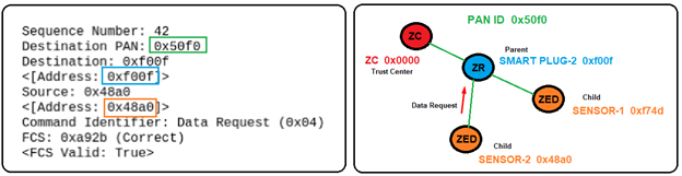
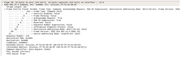
In frame 20, we see the joining device issuing a Data Request command (0x04) to the coordinator 0x0000. The Data Request command is basically used by an end device (Smart Plug) to poll its parent (Coordinator) in order to receive data. In this case, the joining device is wanting confirmation that it is now part of the network (fully joined).
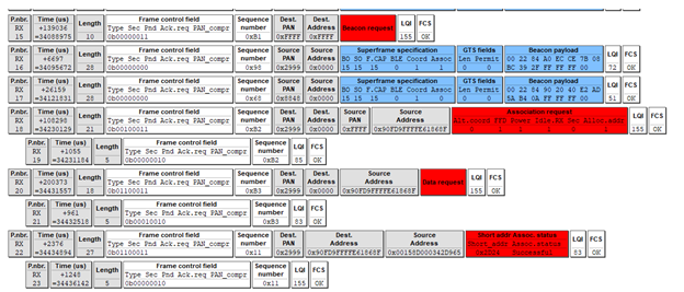
Note: When capturing the ‘Join’ process on this sandboxed Zigbee network, I chose to run two Zigbee sniffers (the API-MOTE with Wireshark and the Texas Instruments CC2531 with PACKET-SNIFFER — SmartRF protocol packet sniffer) concurrently. The following screenshot shows the same information just presented, but as it was displayed with the Texas Instruments Packet Sniffer application.
Packet 15 shows the joining device Beacon Request and packet 16 shows the coordinator’s Beacon Response with the Association Permit bit set to True. (Notice that packet 17 was also captured, but is from a different (nearby) PAN (0x8848), so we can ignore that one.)
Continuing sequentially, packet 18 shows the joining device (EUI-64 long address) Association Request command (sequence number 0xb2). Packet 19 is the Ack for sequence (0xb2).
Packet 20 shows the joining device Data Request command, polling the coordinator for data (confirmation of join status). Notice that the joining device sequence counter incremented to 0xb3. Packet 21 is the Ack for sequence 0xb3.
Packet 22 shows the coordinator (EUI-64 long address) Association Response, sending the requested data to the joining device (EUI-64 long address). The requested data in this case is the assignment of a new node ID (short address 0x2d24) to the joining device and an Association status of Successful. Packet 23 is the Ack for the Association Response.
Keep in mind, this is just a confirmation that the joining device (0x2d24) has successfully joined the network (PAN 0x2999), but the device can not communicate with any of the other devices in the network until it is given the trust center’s network key. In this case, we could say the newly joined device is associated, but not yet authenticated.
Notice that the sequence number increments each time the coordinator communicates with the joining device and each time the joining device communicates with the coordinator. Also, notice that each has its own unique sequence number. This, in combination with unique device frame counters, helps protect the network from replay attacks.
AUTHENTICATION (Getting the Network Key)
When creating my sandboxed Zigbee network, I authenticated the smart plug device out-of-band (OOB) using my mobile phone and the AduroSmart ERIA Home Automation application. This implementation of joining the network uses Install codes (standard on all Smart Energy devices and all devices running Zigbee 3.0 or later).
Using an installation code provides security for the initial exchange of the network key to the device, at the cost of added interaction between the user and the trust center. A user must somehow transfer the key from the device to the trust center. This can be accomplished by a mechanism outside of the Zigbee network (OOB), such as typing the code into the trust center from a label on the device or scanning the associated QR code.
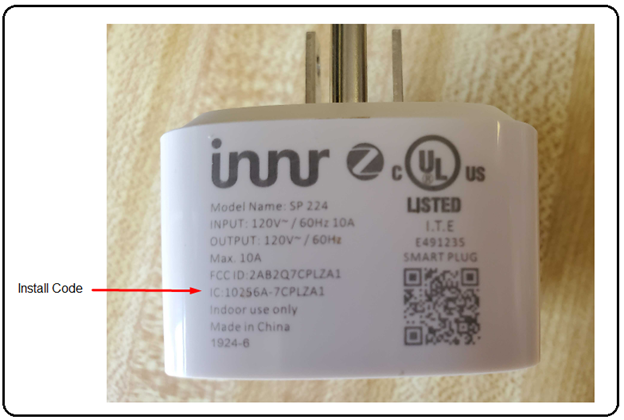
During manufacturing, the Install code is placed in the memory of the device and also printed somewhere on the device (and/or outside packaging). An application within the device submits the Install code as an input to a Matyas-Meyer-Oseas (MMO) one-way compression function (https://en.wikipedia.org/wiki/One-way_compression_function), which outputs a 128-bit hash (pre-configured link key).
This Install code and the EUI-64 (extended) address of the joining device are provided OOB to the coordinator, who uses the same MMO function. Both endpoints can now produce the preconfigured link key used to encrypt and decrypt messages. The preconfigured link key is exclusive (private) to the newly joined device and the coordinator. The coordinator can now securely transport the secret network key (encrypted with the preconfigured link key).
Consequently, even myself, as owner and administrator of this sample (sandboxed) Zigbee network, does not know the actual preconfigured link key. Although, I might be able to obtain it through trial and error (submitting what I believe is the Install code, as an input to the MMO algorithm). Unfortunately, I would still need to verify the authenticity of this key by decrypting a known encrypted payload and validating its plaintext result. Although this is something that I am still pursuing, it is presently beyond the scope of this write-up.
Note: For a relatively short period of time, there existed a preconfigured global link key that was used to allow devices to associate (join) and authenticate to a network. At the time, the Zigbee Alliance felt that the extremely limited amount of over-the-air (OTA) exposure was acceptable, as a trade-off for ease of installation for the end consumer. The value ‘5A 69 67 42 65 65 41 6C 6C 69 61 6E 63 65 30 39′ (Ascii representation of ZigBeeAlliance09) is no longer recognized as a valid global link key in Zigbee 3.0 and later, but still exists in many legacy stacks and devices.
Once the newly joined device receives the network key, all future sensitive communication with the network will be encrypted with this key.
Adding Another Zigbee Device to Our Network
Currently, our Zigbee network has been formed using an ERIA Smart hub as the Zigbee Coordinator (ZC), and an Innr Smart Plug as a Zigbee End Device (ZED). Notice, that even though the Smart Plug is a (never sleeps) full-function device (FFD) and could be a router, it is actually considered a ZED (that never sleeps) until it becomes a parent.
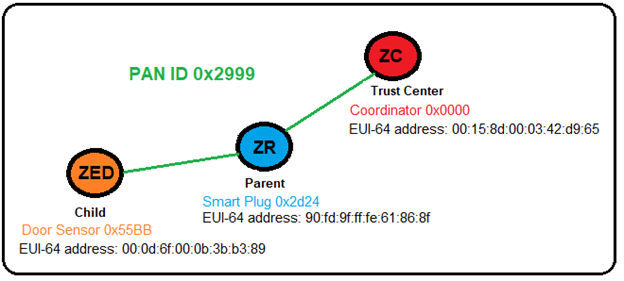
Let’s add a battery-powered door/window sensor Zigbee device to our network. Check out the floor plan of our Zigbee network and pay particular attention to the placement of our devices.
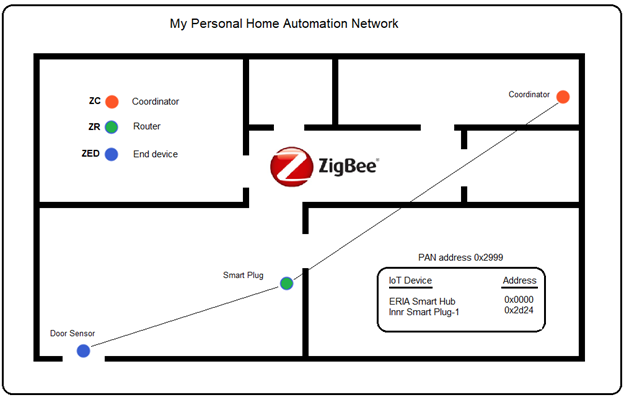
Zigbee networks are self-forming and self-healing mesh networks. What this means is that when a new device joins the network, the (parent) router is chosen based upon relative distance, by determining the shortest route. This allows for more reliable communications (fewer dropped packets) and helps facilitate self-healing should a parent (ZR) fail or be moved to a different unrelated network. In this case, the next closest router (or coordinator) will become the new parent.
In a Zigbee mesh network, the Received Signal Strength Indicator (RSSI) and Language Quality Inspection (LQI) can be used to determine the relative distance between nodes. RSSI is a distance-based network parameter, which is a measurement of radio signal strength, while LQI is a metric of the link quality of the received signal. The (LQI) can be seen at the end of the Texas Instruments packets:
The Radius Field
The radius is a 1-byte value (Zigbee Network Layer) that is used as an indication of how far-reaching a signal is intended to go. For example, a radius of 1 is often useful in communicating to nodes that are in close proximity to each other. The network may be 10 hops in diameter, but if a broadcast is limited to a radius of 1, it will only affect its neighboring nodes. This feature becomes very handy in situations such as hotel rooms, commercial offices, hospital rooms, etc. where controlling various sensors, locks, or equipment specific to a room is needed.
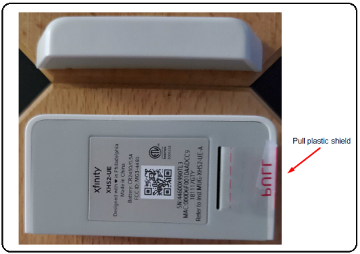
Preparing the sensor for pairing
For previously used sensors, we first need to factory reset the Door Sensor. This can be accomplished by removing the battery, holding down the tamper switch while reinserting the battery. Continue holding down the tamper switch until the LED lights (indicating the factory reset is starting). Immediately release the tamper switch within 4 seconds. The sensor should begin to flash the LED, indicating pairing mode is activated.
Newly purchased devices typically have a plastic tab inserted between the battery and its contacts to prevent it from powering on until it’s ready to be installed. Simply pull the plastic tab from the device, thereby allowing the battery to make contact and power the unit. Immediately upon power-up, the sensor should begin to flash the LED, indicating pairing mode is active.
The pairing mode window will remain open for a few minutes (up to 245 seconds), in which time we need to place the hub in pairing mode (typically, by pressing the power button for 1-2 seconds). If successful, the LED on the hub should begin to flash, indicating pairing mode active.
Sniffing Zigbee traffic
Again, I chose to run two sniffers concurrently, while capturing the join process of the Door Sensor Zigbee device. The following Texas Instruments CC2531 captured packets represent the joining process. Notice that it pretty much mirrors the Smart Plug pairing, with a few new key points.
Like the Smart Plug, the Door Sensor begins with a Beacon Request (frame 338), asking for Beacon Responses from all devices in the network.
As was the case with the Smart Plug, a coordinator from a nearby (unrelated) network (PAN 0x8848) responds with its Beacon (frame 340) but as before, we can ignore this.
So, this leaves two remaining Beacons (frames 339 and 341), which are our coordinator (0x0000) and Smart Plug (0x2d24). In particular, notice that both devices are showing the Association permit bit True, meaning either device is capable of allowing the Sensor to join. Note: Reduced Function Device (RFD) endpoints do NOT issue Beacons.
Based upon the relative proximity of all of the devices, the Smart Plug is chosen as the Sensor’s potential parent, as it is much closer than the coordinator (see floor plan).
Frame 342 shows the Sensor (source) sending an Association Request to the Smart Plug (destination). Because the Sensor is not yet associated with the network, it needs to use its EUI-64 address (0x000d6f000b3bb389). Frame 343 is the Ack for the Association Request (matching sequence number 0x36).
Frame 344 shows the Sensor sending a Data Request to the Smart Plug (0x2d24), polling the Smart Plug for data (confirmation of join status). Frame 345 is the Ack for the Data Request command (sequence number 0x37).
Frame 346 shows the Smart Plug’s (EUI-64 long address) Association Response, sending the requested data to the Sensor’s (EUI-64 long address). The requested data in this case is the assignment of a new node ID (short address 0x55BB) to the Sensor and an Association status of Successful. Frame 347 is the Ack for the Association Response.
At this point, the Smart Plug is no longer considered an end device (ZED). It is a now fully functioning router (ZR) and a parent to its child, the Sensor (ZED).
Our sample Zigbee network now looks like this:
As was the case when the Smart Plug first joined the network, the Sensor has successfully joined the network (PAN 0x2999), but cannot communicate with any of the other devices in the network until it is given the trust center’s network key. The Door Sensor (ZED) is associated, but not yet authenticated.
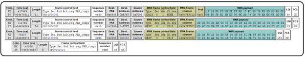
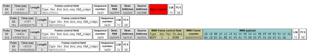
As we stated earlier (and often) in this write-up, the Coordinator is the trust center for all Zigbee Centralized Security networks. So all requests or commands of a sensitive nature must be made to the trust center, the coordinator (ZC). In order to accomplish this, the Door Sensor (ZED) must use its parent (ZR) to relay the Data Request to the (ZC).
Notice that frame 350 shows the Sensor (source) sending the Data Request to its parent, the Smart Plug (ZR). Frame 351 is the Ack for the Data Request.
Frame (352) shows the Smart Plug (source) forwarding a network payload to the (ZC). Frame 353 is the Ack for frame353.
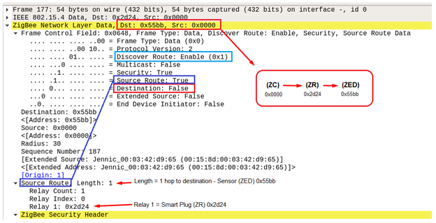
The following Wireshark screenshot shows a Zigbee Network layer data frame (177), where the source is the Coordinator (ZC) and the intended destination is the Sensor (ZED), using the Smart Plug (ZR) as the relaying router. Notice ‘Security: True’. This is a good example of the trust center (ZC) sending sensitive data to a child device (ZED), via the child’s parent (ZR).
To complete this Zigbee project, we will commission two more Zigbee devices into the network: Innr Smart Plug #2 and Xfinity Door Sensor #2. Check out the modified floor plan of our Zigbee network, and again, pay particular attention to the placement of our devices.
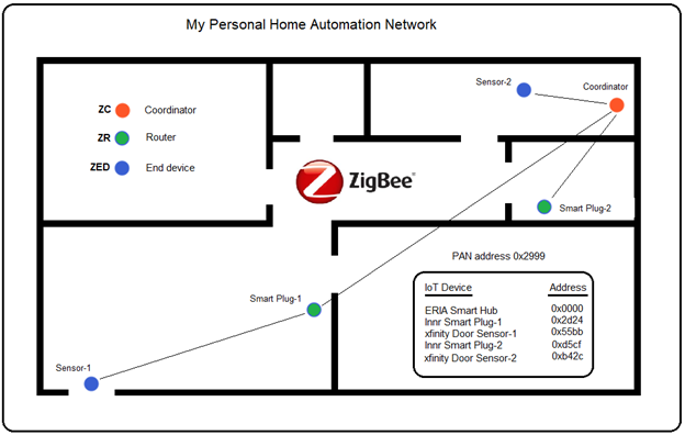
As we can see, we have one coordinator (ZC) which is the trust center of the network. We have two routers (ZR) that function as smart plugs, and we have two end devices (ZED) that function as sensors. Also, we can see that Smart Plug-1 is the parent of Sensor-1, while the Coordinator is the parent to Sensor-2, Smart Plug-1, and Smart Plug-2.
Although this arrangement of devices is fine for small home networks that are well within range of the coordinator, ideally it would be more beneficial to move the coordinator to the center of the network’s target area. This becomes even more important when automating large commercial properties with hundreds of possible nodes.
Summary
The undertaking of this project proved to be extremely exhaustive and required navigating to many sites to acquire the information necessary to produce this write-up. Occasionally, I would find that the material being presented was either outdated, incorrectly explained, or lacking the technical information necessary for an in-depth discussion of the Zigbee wireless protocol.
Hopefully, by weeding out much of the irrelevant or incorrect information and by deep-diving into a number of certified Zigbee specifications (Zigbee Alliance, Silicon Labs, Texas Instruments, etc.), the material presented in this write-up offers the reader a clear and concise understanding of how it all comes together. Keep in mind, variants in the Zigbee stacks (legacy or vendor related) do exist and always need to be considered (as with any evolving technology) when doing your own research or development.
For myself, some of the key takeaways I’ve learned from this project are that Zigbee offers a complete solution to home and commercial automation of the internet of things (IoT). In particular, Zigbee’s mesh-networking offers ranges that can far exceed the 10-100 meter limitation for individual devices, by implementing a self-forming and self-healing network. Literally, thousands of devices can theoretically communicate on a mesh network at far-reaching distances, while still maintaining reliable, low-power communication between nodes.
Remarkably, Zigbee’s constantly evolving security infrastructure is in a league of its own. Its security architecture complements the security services provided by IEEE 802.15.4 standard. Zigbee’s security is based on an open trust concept, where the protocol stack layers trust each other, and that the layer that originates a frame is responsible for initially securing it. The secret keys are not inadvertently revealed during key transport. Moreover, the introduction of Install Codes in Zigbee 3.0 (mandatory in previous SmartThings stacks) is a highly secure way to transport keys, where no key is ever transported in plaintext over-the-air (OTA). Additionally, Zigbee’s use of individual device frame counters and sequence numbers, and the implementation of the Message Integrity Code (MIC) as a deterrent, ultimately make replay attacks highly unlikely. Add to this the realization that the coordinator (Trust Center) can change the Network key at any time that it feels the security of the network might be compromised, which makes for an extremely secure network.
In closing, it is my intent to continue my research of the constantly evolving Zigbee protocol. In particular, I intend on focusing much of my ongoing research pertinent to the recent implementation of Install Codes in Zigbee 3.0, as I feel that this is going to be the de facto standard going forward. Specifically, I’m very much interested in discovering the Install Code of one of my devices, submitting it as the input to a Matyas-Meyer-Oseas (MMO) hash function, and using the resultant 128-bit link key to decrypt the highly evasive encrypted Network key on my Zigbee network. This could very well be the groundwork for a follow-up blog, “Inside Zigbee Security.” Stay tuned.
Research and useful links
https://zigbeealliance.org/solution/zigbee/
https://zigbeealliance.org/news_and_articles/step-by-step-guide-getting-started-with-zigbee/
https://community.silabs.com/s/?language=en_US
https://docs.silabs.com/zigbee/6.6/em35x/group-ember
https://www.silabs.com/developers/zigbee-emberznet
https://www.silabs.com/developers/simplicity-studio
https://news.silabs.com/2012-07-09-Silicon-Labs-Completes-Acquisition-of-Ember
https://www.silabs.com/documents/public/user-guides/ug103-01-fundamentals-wireless-network.pdf
https://www.silabs.com/documents/public/user-guides/ug103-02-fundamentals-zigbee.pdf
https://www.silabs.com/documents/public/user-guides/ug103-03-fundamentals-design-choices.pdf
https://www.silabs.com/documents/public/application-notes/an1233-zigbee-security.pdf
https://github.com/SiliconLabs/IoT-Developer-Boot-Camp/wiki/Zigbee-Preparatory-Course
https://www.silabs.com/support/training/mesh
https://www.ti.com/tool/Z-STACK
https://www.ti.com/tool/PACKET-SNIFFER
https://en.wikipedia.org/wiki/Zigbee
https://research.kudelskisecurity.com/2017/11/08/zigbee-security-basics-part-2/
https://www.zigbee2mqtt.io/information/zigbee_network.html
https://www.sciencedirect.com/topics/computer-science/zigbee-end-device
Ready to learn more?
Level up your skills with affordable classes from Antisyphon!
Available live/virtual and on-demand