Using Infrared for Hardware Control
Ray Felch //

Overview
Infrared technology has been around for a very long time and is a wireless technology used in devices that convey data by way of Infrared radiation. Infrared is electromagnetic radiation (EMR) with a wavelength just beyond the visible light spectrum. Inasmuch, Infrared can not be seen by the naked eye, Fun fact: Although Infrared can not be seen by our eyes, the camera on your phone can capture and display these transmissions just fine!
As you are probably aware, Infrared technology is used in a great number of applications, such as thermal Imaging cameras, medical applications, military applications (target acquisition, night vision, etc), heating and cooling, and computer peripheral communication, just to name a few.
The goal of this write-up is to show just how easy it is to not only capture Infrared communication but also to replay the transmission. Initially, I’ll show how I was able to capture the IR signals of a couple of remotes I had laying around the house, using Infrared tools available in most Linux repos.
Hacking Infrared television remote controls might seem a bit impractical at first glance, however, it can be done very easily and costs practically nothing to accomplish. The wealth of information regarding the Infrared process is most definitely worth the effort. As part of my research, I decided to capture the Infrared button presses of a Kodi (open source media player) remote, an Arduino generic remote, and an HDMI switch remote. I was amazed at how quick and easy it was to retrieve this data!
Objectives
- Getting familiar with the NEC IR protocol
- Using a Raspberry Pi and Linux drivers to detect and transmit IR remote codes
- Using IR and Mega2560 module to control relays
IR Protocols (general info)
In general, an IR Protocol is a set of rules that specify how to transmit a group of bits or bytes. There is a transmitting device (IR emitter diode) which sends these pulses at a specific frequency for a specific amount of time and then pauses for a specific amount of time. Each bit, 0 or 1, is encoded with a specified combination of these timings, which in turn allows for the IR receiver to properly read the transmission. There are quite a few Infrared protocols, but three of the more popular follow:
NEC is a well-known protocol and perhaps is the most widely used. It was developed by NEC and has been adopted by many companies. Its waveform is made of a start frame, a bitstream, and an end of message terminator.
The NEC IR transmission protocol uses pulse distance encoding of the message bits. Each pulse burst is 562.5µs in length, at a carrier frequency of 38kHz. Logical bits are transmitted as follows:
Logical ‘0’ – a 562.5µs pulse burst followed by a 562.5µs space, with a total transmit time of 1.125ms
Logical ‘1’ – a 562.5µs pulse burst followed by a 1.6875ms space, with a total transmit time of 2.25ms
When a key is pressed on the remote controller, the message transmitted consists of the following, in order:
- 9ms leading pulse burst (16 times the pulse burst length used for a logical data bit)
- 4.5ms space
- 8-bit address for the receiving device
- 8-bit logical inverse of the address
- 8-bit command
- 8-bit logical inverse of the command
- final 562.5µs pulse burst to signify the end of message transmission
The four bytes of data bits are each sent least significant bit first.
SIRC is a proprietary protocol by SONY and three variants exist (12, 15, or 20 bits). In all variants, the command field has a fixed length of 7 bits. All the information bits are streamed least significant bit first.
- 12-bit version, 7 command bits, 5 address bits.
- 15-bit version, 7 command bits, 8 address bits.
- 20-bit version, 7 command bits, 5 address bits, 8 extended bits.
- Pulse width modulation.
- Carrier frequency of 40kHz.
- Bit time of 1.2ms or 0.6ms.
PHILIPS RC5 & RC6 PROTOCOL
RC5 / RC6 Manchester
RC5 and RC6 are two different protocols by Philips, both based on the Manchester coding. Their carrier frequency is set at 36KHz with a recommended PWM duty cycle of 1/4 or 1/3 but not mandatory.
In Manchester coding the bit time is provided by a constant clock, so both the values 1 and 0 take the same amount of time but in one case the pulse precedes the pause (here this is a logical 0), in the other is the opposite (here this is a logical 1).
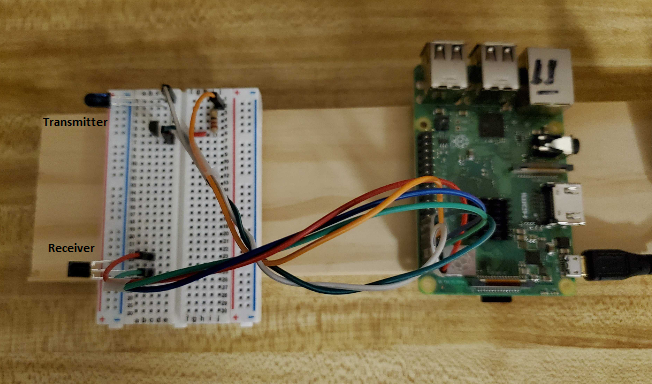
Transmitting and Receiving Infrared signals
Using a Raspberry Pi and Linux IR drivers
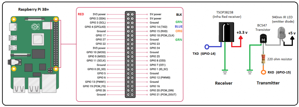
Getting familiar with transmitting and receiving Infrared communication can be accomplished fairly quickly using a Raspberry Pi with Raspbian (Buster), an Infrared Linux tool, a few components (TSOP38238 receiver, 940nm emitter diode, and 220-ohm resistor), and some hookup wires. Understanding the intricacies of the various protocols is not necessary, as the work has been done for us, within the Linux drivers.
Using ir-keytable (a swiss-knife tool to handle Remote Controllers) and the aforementioned circuit, we can detect and decipher remote control button presses. http://manpages.ubuntu.com/manpages/bionic/man1/ir-keytable.1.html
Customize config.txt:
As part of this configuration, IR transmission is also configured. If transmission is not needed, exclude dtoverlay=gpio-ir-tx,gpio_pin=15. Some of the output might be different as a result.
Update config.txt variables:
pi@rasp11:~/infra-red $ sudo nano /boot/config.txt
  # BEGIN ADDED
  dtoverlay=gpio-ir,gpio_pin=14
  #dtoverlay=gpio-ir-tx,gpio_pin=15
  # END ADDED
Reboot:
pi@rasp11:~/infra-red $ sudo reboot
Confirm gpio modules are loaded:
pi@rasp11:~/infra-red $ lsmod | grep gpio
gpio_ir_recv 16384 0
List devices:
cat /proc/bus/input/devices
  I: Bus=0019 Vendor=0001 Product=0001 Version=0100
  N: Name="gpio_ir_recv"
  P: Phys=gpio_ir_recv/input0
  S: Sysfs=/devices/platform/ir-receiver@e/rc/rc0/input4
  U: Uniq=
  H: Handle rs=kbd event4
  B: PROP=20
  B: EV=100017
  B: KEY=fff 0 0 4200 108fc32e 2376051 0 0 0 7 158000 4192 4001 8e9680 0 0 10000000
  B: REL=3
  B: MSC=10
Install ir-keytable:
pi@rasp11:~/infra-red $ sudo apt-get install ir-keytable -y
Confirm install:
pi@rasp11:~/infra-red $ ir-keytable
  Found /sys/class/rc/rc0/ (/dev/input/event4) with:
    Name: gpio_ir_recv
    Driver: gpio_ir_recv, table: rc-rc6-mce
    LIRC device: /dev/lirc0
    Attached BPF protocols: Operation not permitted
    Supported kernel protocols: other lirc rc-5 rc-5-sz jvc sony nec sanyo mce_kbd rc-6 sharp xmp imon
    Enabled kernel protocols: lirc rc-6
    bus: 25, vendor/product: 0001:0001, version: 0x0100
    Repeat delay = 500 ms, repeat period = 125 ms
Test remote:
pi@rasp11:~/infra-red $ sudo ir-keytable -p all
Protocols changed to other lirc rc-5 rc-5-sz jvc sony nec sanyo mce_kbd rc-6 sharp xmp imon
Confirm IR Receiver device is working:
pi@rasp11:~/infra-red $ sudo ir-keytable
 Found /sys/class/rc/rc0/ (/dev/input/event4) with:
    Name: gpio_ir_recv
    Driver: gpio_ir_recv, table: rc-rc6-mce
    LIRC device: /dev/lirc0
    Attached BPF protocols:
    Supported kernel protocols: other lirc rc-5 rc-5-sz jvc sony nec sanyo mce_kbd rc-6 sharp xmp imon
    Enabled kernel protocols: lirc rc-5 rc-5-sz jvc sony nec sanyo mce_kbd rc-6 sharp xmp imon
    bus: 25, vendor/product: 0001:0001, version: 0x0100
    Repeat delay = 500 ms, repeat period = 125 ms
- Notice device found as rc0
Note About rc0 and rc1:
Normally the IR receiver is assigned to /sys/class/rc/rc0. However, due to the nature of multi threaded device probe, the receiver device can be assigned to /sys/class/rc/rc1
In the following notes, when ir-keytable is called with -s rc0 and there is no response or an error, use -s r1. If no -s is specified, rc0 is default. However, due to the possibility of the receiver being assigned to rc1 during boot, it is recommended to always specify -s. In this way, if the ‘wrong’ device is used an error will appear.
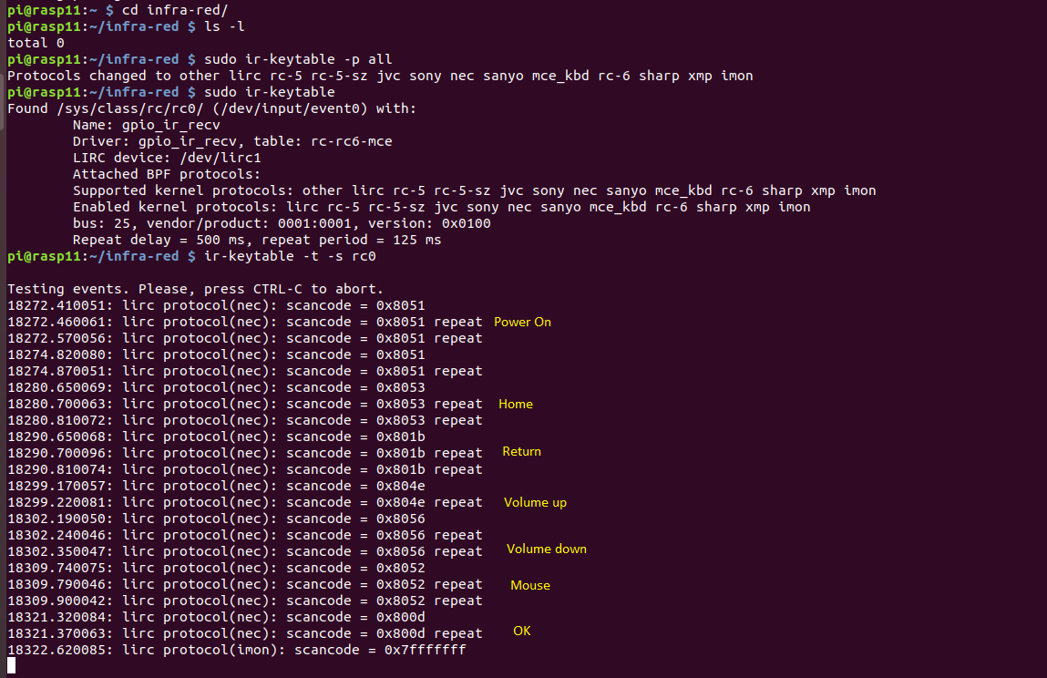
Test remote with rc0 (scan button presses loading all protocols):
pi@rasp11:~/infra-red $ ir-keytable -t -s rc0
Testing events. Please, press CTRL-C to abort.
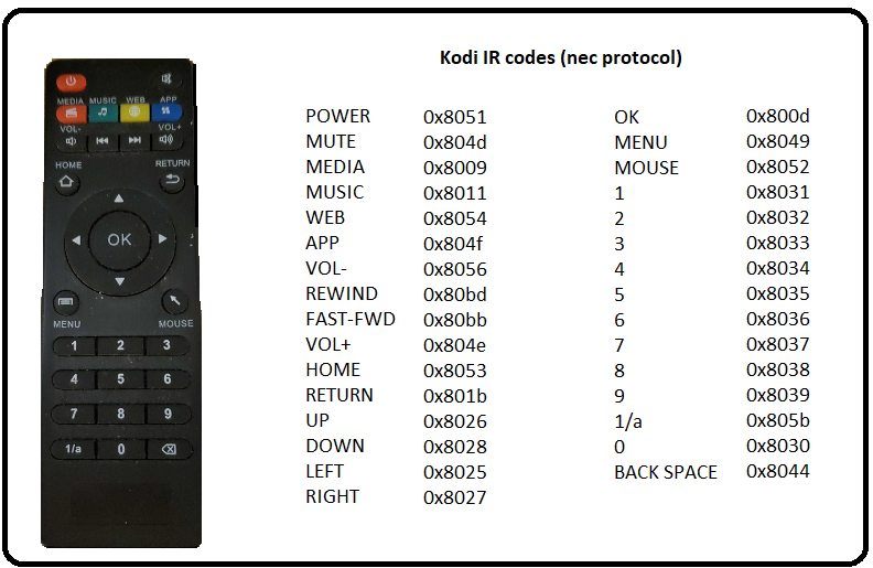
Sample readings on Kodi remote
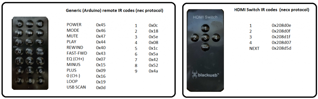
Captured codes of all three remote controls
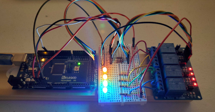
Hardware control using Infrared
Using IR and Mega2560 module to control relays
- Generic remote control
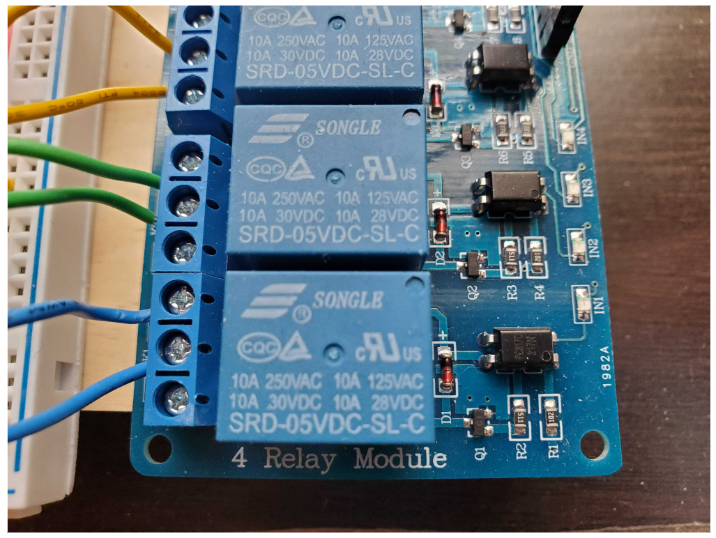
- Sainsmart 4 channel relay module
- Mega2560 module
For this project, we’ll be using an Elegoo Mega2560 R3. The Mega2560 is a microcontroller board based on the ATmega2560. It has 54 digital input/output pins (of which 15 can be used as PWM outputs), 16 analog inputs, 4 UARTs (hardware serial ports), and a 16 MHz crystal oscillator.
This module is comparable to an Arduino Uno on steroids and at the time of this writing, reasonably priced at just under $40. It is compatible with most shields designed for the Uno and supports flash memory configuring with the Arduino IDE software environment.
For this demonstration, I have chosen to attach LEDs to each of the four relays for a visual indication of relay closure. It should be noted that the Sainsmart relays can be configured to control a vast variety of AC/DC hardware such as lighting, motors, sensors, etc, and are limited only by the voltage/current ratings of the relay chosen. The module used in this demonstration is a four-channel 5-volt relay module capable of handling up to 10A @ 120VAC or 10A @ 28VDC. Each relay provides a normally open or normally closed configuration. I chose to use the normally open set of terminals (LED’s normally off).
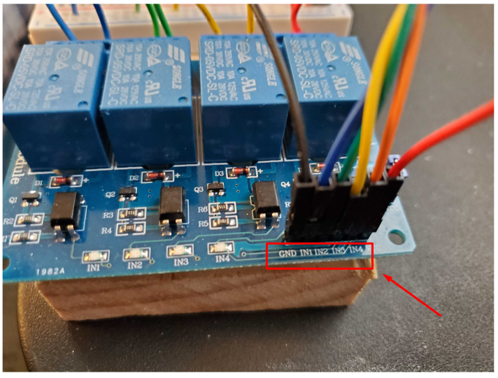
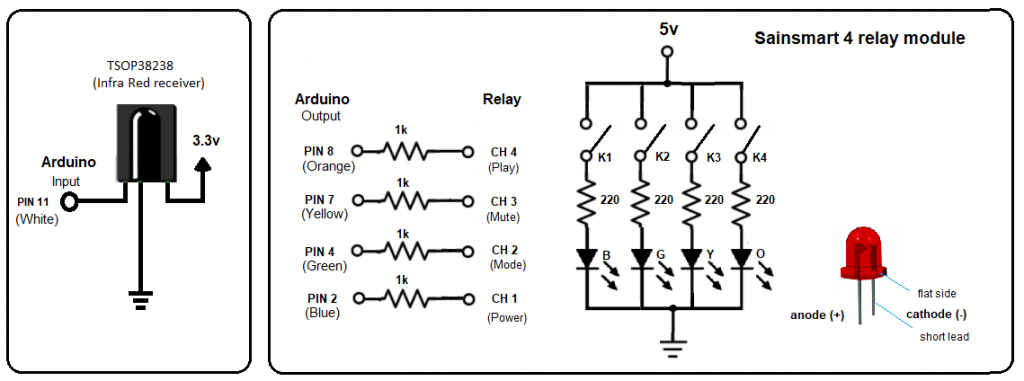
Control of the four individual relays is pretty straightforward and shown below. To engage a specific relay and activate its corresponding LED the specific input control pin (IN1 – IN4)) needs to be pulled low (GND).
Circuit diagram
Using the Arduino IDE to flash the Mega2560
The following sketch will look for button presses on the Arduino generic remote. Specifically, this sketch will monitor for the ‘power’, ‘mute’, ‘mode’ and ‘play’ buttons (codes: 0x45, 0x46, 0x47, 0x44 respectively) and upon discovery will engage the corresponding relay channel (IN1 – IN4) to toggle the channel’s LED.
Pins 39, 37, 35, and 33 on the Mega2560 are defined as output (normally high) and will be pulled low upon discovery of the specific IR code.
SainsmartIR.ino
// Arduino sketch to capture infrared codes and close/open relays based on matching criteria
// Modified NeoPixel_IR sketch from Adafruit_CircuitPlayground, using IRLibAll library
// Written to interface with Sainsmart 4 relay module.
// Author: R.F. Felch 01/28/2021
#include
//IRrecv myReceiver(11);//receiver on pin 11 //Arduino Uno
IRrecv myReceiver(11);//receiver on pin 32 //Mega2560
IRdecode myDecoder;//Decoder object
// Arduino Uno
//int play = 8;
//int mute = 7;
//int mode = 4;
//int power = 2;
// Mega2560
int play = 39;
int mute = 37;
int mode = 35;
int power = 33;
// Channel status false = Relay open true = Relay closed
bool CH_1 = false;
bool CH_2 = false;
bool CH_3 = false;
bool CH_4 = false;
void setup() {
pinMode(power, OUTPUT); // Relay channel 1
pinMode(mode, OUTPUT); // Relay channel 2
pinMode(mute, OUTPUT); // Relay channel 3
pinMode(play, OUTPUT); // Relay channel 4
// Set channels high open relay
digitalWrite(power, HIGH);
digitalWrite(mode, HIGH);
digitalWrite(mute, HIGH);
digitalWrite(play, HIGH);
Serial.begin(115200);
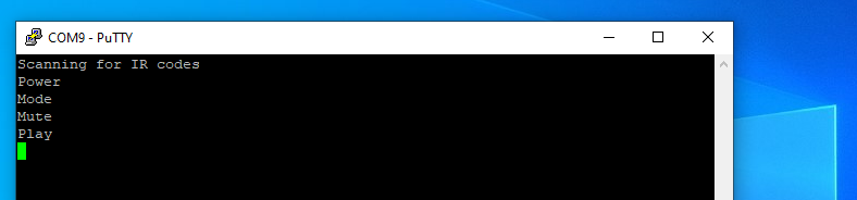
Serial.println("Scanning for IR codes");
myReceiver.enableIRIn(); // Start the receiver
}
void loop() {
if (myReceiver.getResults()) {
myDecoder.decode();
if (myDecoder.protocolNum == NEC) {
//Serial.println(myDecoder.value); // uncomment to view captured values
switch(myDecoder.value) {
case 0xffa25d: //Power
Serial.println("Power");
if (CH_1 == false) digitalWrite(power, LOW); // close relay ch-1
if (CH_1 == true) digitalWrite(power, HIGH); // open relay ch-1
CH_1 = !CH_1;
break;
case 0xff629d: //Mode
Serial.println("Mode");
if (CH_2 == false) digitalWrite(mode, LOW); // close relay ch-2
if (CH_2 == true) digitalWrite(mode, HIGH); // open relay ch-2
CH_2 = !CH_2;
break;
case 0xffe21d: //Mute
Serial.println("Mute");
if (CH_3 == false) digitalWrite(mute, LOW); // close relay ch-3
if (CH_3 == true) digitalWrite(mute, HIGH); // open relay ch-3
CH_3 = !CH_3;
break;
case 0xff22dd: //Play
Serial.println("Play");
if (CH_4 == false) digitalWrite(play, LOW); // close relay ch-4
if (CH_4 == true) digitalWrite(play, HIGH); // open relay ch-4
CH_4 = !CH_4;
break;
}
myReceiver.enableIRIn(); //Restart the receiver
}
}
}
Typical run of Arduino generic remote button presses
Conclusion
For me, this was an enjoyable project from the very beginning and although Infrared communication has been around for quite some time, it’s nice to know that we have open source tools available to help us with our research.
Additionally, it was interesting to learn that the Infrared wavelength is just outside of the visible light spectrum and invisible to the naked eye. I recently discovered that a team of researchers used this information as a means to exfiltrate and infiltrate proprietary data on an air-gap security camera network. https://arxiv.org/abs/1709.05742
Using malware installed internally on the network they managed to establish bi-directional covert communication between the internal network of organizations and remote attackers by controlling (pulsating) the IR illumination. The researchers indicated that they were able to exfil PIN codes, passwords, and encryption keys at a rate of 20 bits/sec and infil data into the network at a rate of 100 bits/sec. They went on to say that binary data such as command and control (C2) and beacon messages were encoded on top of the IR signals.
Ultimately, I found that it was quite easy to configure hardware to harness the power of Infrared and control relays with a push of a button. The benefits of Infrared hardware control are practically limitless, limited only by the imagination of the hardware designer.
Ready to learn more?
Level up your skills with affordable classes from Antisyphon!
Available live/virtual and on-demand