How to Hack Hardware using UART
Preface:
I began my exploration of reverse-engineering firmware a few weeks back (see “JTAG – Micro-Controller Debugging“), and although I made considerable progress finding and identifying the JTAG (Joint Test Action Group) pins on my target board (Samsung S3C4510 CPU) Linksys BEFSR41 router, there were complications. I ran into a number of issues while attempting to extract the firmware using OpenOCD and a few different JTAG adapters (including using a home-brew Raspberry Pi3 as a JTAG and SWD adaptor (see: https://movr0.com/2016/09/02/use-raspberry-pi-23-as-a-jtagswd-adapter), which worked well and got around the speed control limitations of the Bus Pirate.
In some cases, I was able to dump memory from the flash device, but the data was erratic and unrecognizable when using the binwalk tool. This may be a timing-related issue, or possibly not getting the target in the proper halt state prior to reading memory. I also realize that from time to time, vendors may take precautions in guarding their proprietary information, either by tying reset pins high or opening critical JTAG paths by way of deliberately blowing fuses after production testing. My list of unknown issues is increased even further due to the fact that this is a ‘used’ board of questionable state.
Understanding and implementing the OpenOCD (Open source On-chip-debugger) was a huge undertaking in itself. To quote from Wikipedia, “OpenOCD is a free software on-chip debugging, in-system programming and boundary-scan testing tool for various ARM and MIPS systems.” The OpenOCD server accepts commands remotely through TCP/IP ports and provides an interface that allows for interacting with the on-board devices. This interface can be through Telnet port 4444 or using GDB (GNU Debugger) on port 3333.
Choosing a new router and a new approach
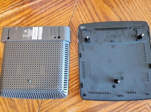
After much frustration (and needing a “win’), I chose to temporarily take a break from this project and try a different (yet similar) approach to gaining access to the firmware. Note: Before undertaking this project, I decided that I wanted to start with a known good device, so I purchased a new router from my local electronics retailer, a Linksys E2500 v3.

The tear-down for this router was pretty simple. Remove the three screws from the bottom of the router and the housing shell can be separated fairly easily using a plastic shim.
Finding the UART TAP
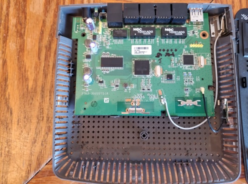
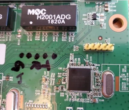
As I did with the JTAG approach, I examined the board for groups of pins that may provide serial access (TX RX GND). Immediately, I saw a point on the board with 5 pins (marked JD6) that I felt might be a possible serial port access point. To make life easier, I soldered in a 5-pin header.
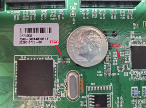
By the way, and just for the record, I did find the JTAG access points on this board (they were clearly marked TDI, TDO, TCK and TMS.) There were a set of access points by the CPU (BCN5358 MIPS) and another set by the Broadcom Radio chip (BCM43236), indicating to me, that it was very likely that there were multiple boundary-scan devices on this board. Unfortunately, the land areas were so microscopic there would be no way for me to attach to them even if I wanted to, thereby making my serial approach that much more appealing.
The JTAGulator is my friend
I quickly found the GND (ground) pin DJ6-5 using my multi-meter by checking for continuity from each pin to a metal shield on the board (this is done with no power applied to the board.) Knowing which pin was ground, I used my favorite hardware tool, the JTAGulator and connected the remaining 4 pins to channels 0 – 3. I also jumpered my GND pin to GND on the JTAGulator.
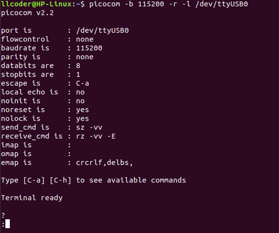
All connected and ready to go. I applied power to the target board and to the JTAGulator. I fired up PICOCOM and immediately got my prompt:
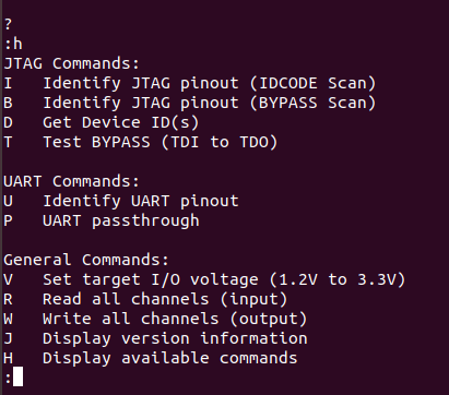
Typing H gets me the help menu, and as noted there were UART commands available to me for finding the necessary pins TX and RX.
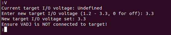
Before continuing, we need to set the target I/O voltage. This is accomplished using the V command:
Now we are ready to issue the U command to find our TX and RX pins. As noted, we need to let the JTAGulator know how many channels we need (number of pins) to check.
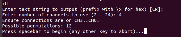
Upon hitting the space-bar to begin, the JTAGulator tries many different baud rates in order to find the best fit. By evaluating the findings, we can quickly determine there appears to be a lot of communication at the 115200 baud rate. Also notice, regardless of the baud rate the JTAGulator seems to find the same pins for TX and RX.
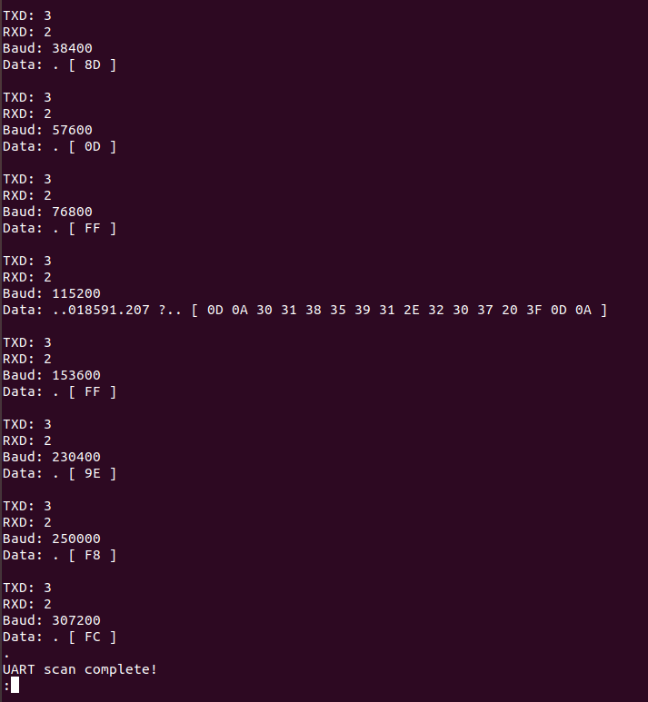
Final results: channel 3 is going to the TX (DJ6 pin 2), channel 2 is going to the RX (DJ6 pin 3) and the baud rate is 115200. Further testing can be done entering the Passthrough mode, allowing us to actually communicate with the chip. This is done by issuing the P command:
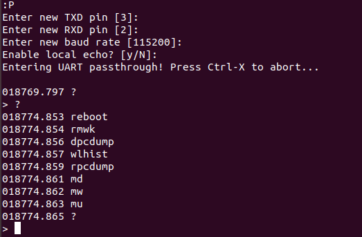
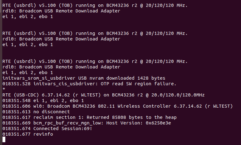
As you can see, I was able to get a list of the commands available to me for this device. Issuing a reboot command rebooted the router, also providing me with relevant information about the device. It appears that I’m talking to the Broadcom Radio chip (BCM43236) using their proprietary wl driver.
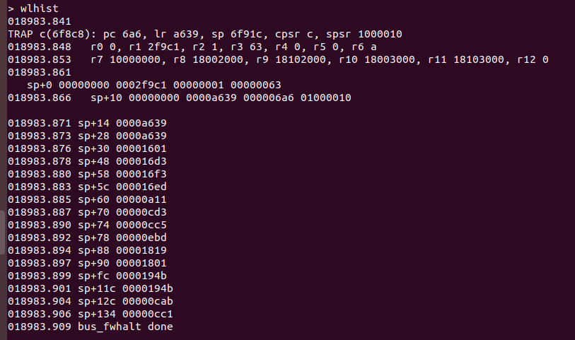
Playing around a bit I tried the wlhist command that dumped the stack and rebooted itself.
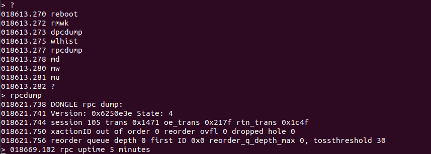
I then tried the rpcdump command and it provided Dongle information, interesting, but not that useful.
While following an interesting blog entitled ‘Reverse-Engineering Broadcom Wireless Chipsets‘ from the people at Quarkslab.com, I noticed they were able to dump memory using a tiny PySerial script that would implement the ‘md’ command for a memory dump request. I attempted many times to do this and was only marginally successful. During my attempts I found that I could only snag just under 2k of data before the chip recognized the intrusion and rebooted itself, thereby aborting the command and inasmuch, killing my script before the bin file could be written. I found that if I shortened my dump to 1K (1024) of data that I could get the data and generate tiny 1k bin files, again not that useful in itself.
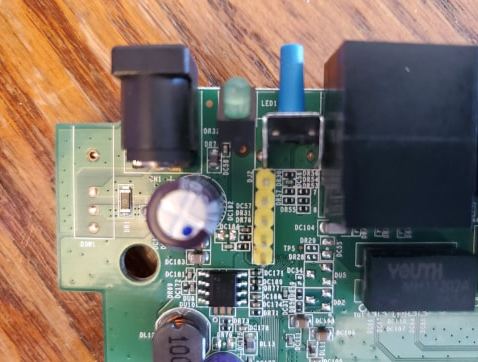
Finding UART TAP number 2
Realizing that I had very few commands provided to me to work with, and also recognizing how secure this chipset might be, I decided to continue looking for another serial access point that might get me connected to the Broadcom CPU directly. I need to mention that at one time during my many Google searches, I did run across a message in a firmware download forum, where it was mentioned that the E2500 router did actually have two serial port TAPs, and one was useless (DJ6 Radio chip 43236) for trying to unbrick their firmware. This was the motivating factor in my attempts to locate this other TAP. In fact, my efforts did find me another set of pins very similar to the first set. Again, there were 5 pins clearly marked DJ2, and again I soldered in a 5-pin header.
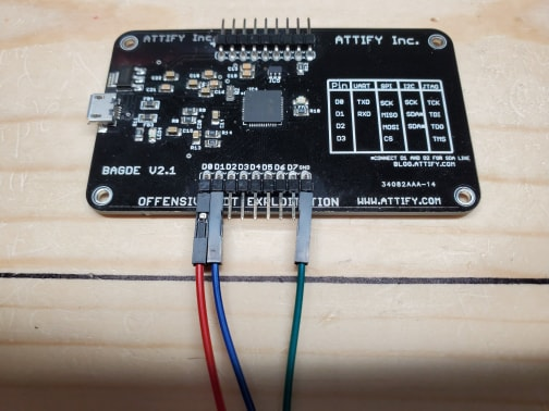
Rather than continue to use the JTAGulator as a serial dongle, I decided at this time to use my Attify Badge as my UART interface. The reason for this is twofold, the JTAGulator (although not overly expensive), is still 3 or 4 times the cost of the badge and I didn’t want to risk damaging this invaluable tool. Also, the Attify badge is geared more to serial communications with its support for UART, SPI and I2C serial protocols (as well as JTAG). The setup is straight forward, D0 and D1 are TX and RX respectively and GND is D8.
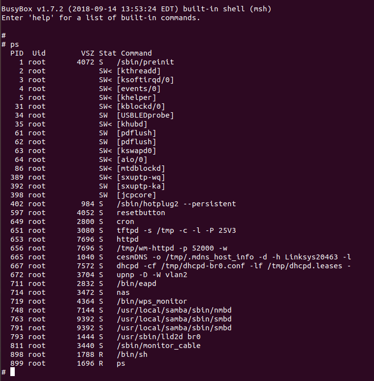
Immediately upon powering up the target board using the new TAP (Test Access Point) DJ2 and the Attify badge, I was presented with a root shell from BusyBox.
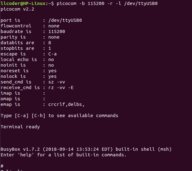
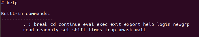
Typing ‘help’ got me a bunch more commands and I went for ‘login’ right away. Trying the usual admin:admin and admin:password attempts got me failed attempts and I went with the standby Ctrl-C a few times. Anyway, after seeing a lot of text fly by, my terminal finally came back to me with the ‘#’ prompt. In fairness, it is possible that I could have typed the password wrong to start with, but regardless I was dropped into root shell.
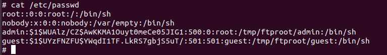
Starting with a quick >ls -la, I was off traversing the many directories (and sub-directories) looking for anything of interest (configuration files, log files, etc), and issuing various commands (ps, netstat, etc).
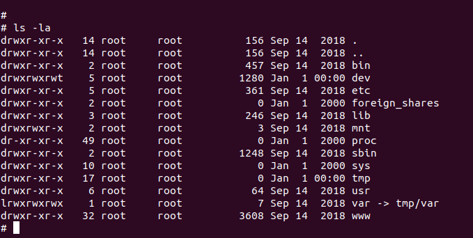
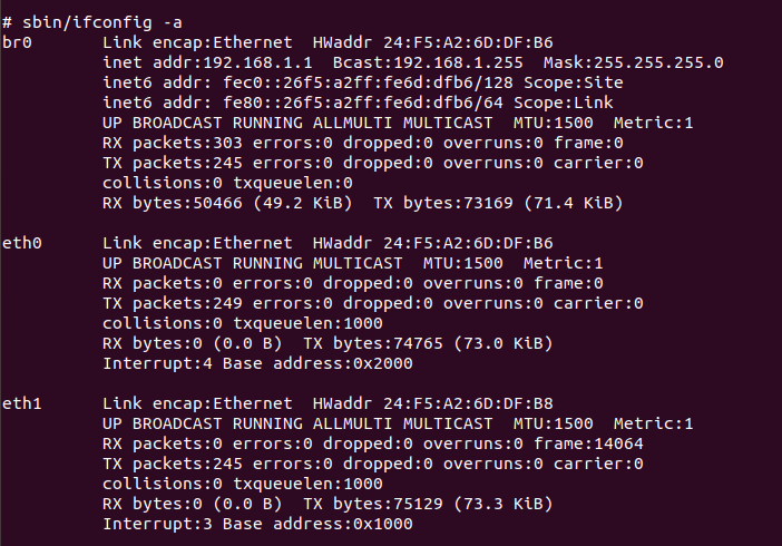

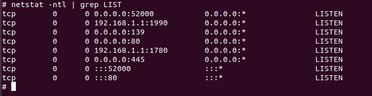
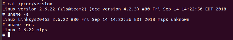
It appears that I’m at the heart of the firmware and in a Linux shell, which was my objective all along, dumping the firmware in order to eventually analyze the code (reverse-engineer) to learn the environment and determine what the code was doing. I did perform a few checks to see if I could Telnet into the router via port 23, and/or SSH in via port 22. Both attempts were refused, so that’s a good thing from the standpoint of router security, however allowing me root access without the proper credentials, in my opinion, is not a smart move.
In summary, I’d say that this was an enjoyable venture, and with relatively quick results as well. I’ve learned that there are other ways to gain access to hardware in addition to JTAG. Finding two UART serial ports and using new devices (Attify badge, JTAGulator) to connect to them proved to be very productive alternative solutions.
Ready to learn more?
Level up your skills with affordable classes from Antisyphon!
Available live/virtual and on-demand