Offensive IoT for Red Team Implants (Part 3)

This is part three of the blog series, Offensive IoT for Red Team Implants. We will be building off from where we left off in the last post, which can be found here: PART TWO
If you have not already read the previous blog posts, I would encourage you to do so first and then come back here.
In the last post, we walked through how to use a Raspberry Pi Pico as a USB rubber duck and extended its capability using an attached LoRa modem to allow for over-the-air execution of DuckyScript files.
In this post, we are going to go one step further, using everything we have learned thus far and ramping it up to 11.
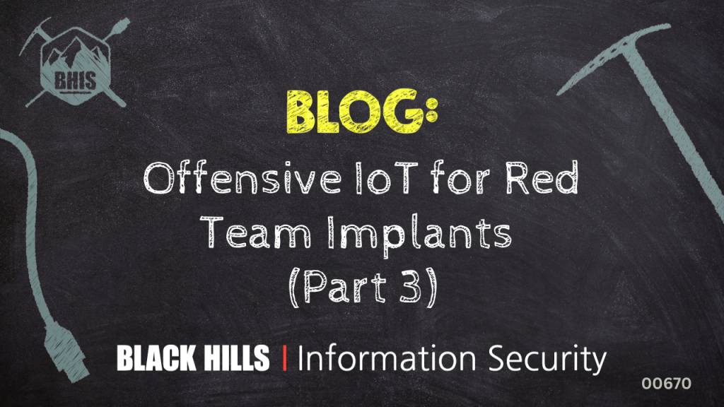
If you recall, in the first blog of this series, I showed an example of Raspberry Pi Zero W with a RM95 LoRa module attached to the header pins.
Well, we are going to use that setup as hardware for the remainder of this post, along with one of the custom Pico/LoRa PCBs from the previous blog post, but that could easily be substituted for an Adafruit Feather RP2040 with LoRa or the like.
Below is the hardware that will be used:
Implant Hardware –
- Raspberry Pi Zero W
- USB Dongle Boarb for Pi Zero
- RFM95 LoRa Module on Breakout board
- 915MHz u.fl Antenna
Operator Hardware –
- Pico-LoRa Breakout Board
- Or Adafruit Feather RP2040 with LoRa: https://www.adafruit.com/product/5714
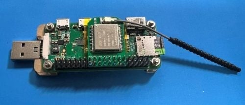
One note on the USB Dongle board for the Pi Zero – there are multiple options but, far and away, my preferred version is the Geek Pi USB Dongle Expansion Board, which can be bought on Amazon for about $11: https://www.amazon.com/GeeekPi-Dongle-Expansion-Raspberry-Inserted/dp/B098JP79ZX.
There are other options; as I said, I have tried most of them and all do work for this purpose. The entire objective of these USB boards is to provide the ability to connect the implant over a USB Type A port, like you would a USB drive, instead of needing cables to power the Pi and transfer data.
For the remainder of this blog post, we are going to focus on configuring the Pi Zero so that it presents itself to a target computer as a USB ethernet device and automatically assigns it an IP address so that the implant and the host can communicate over TCP/IP.
In my opinion, this is the hardest but most critical part of the setup in using a Pi Zero as a physical implant. Unlike the Raspberry Pi Pico, which is rather limited, having the full-fledged Linux computer as your implant is a very powerful tool and having the ability to have the host communicate back to the implant is imperative for this to maximize the potential of the platform.
Diving In
Once you have your hardware ready, you will need to install an OS on a MicroSD card. I would recommend using Raspbian as well as the Raspberry Pi Imager software to install the OS on the card. When doing this, it’s advised that you enable SSH and configure Wi-Fi, as it will make it easier to just plug the Pi Zero W into your host and get started.
After the SD card is ready, insert into the slot and plug your USB Dongle into a computer. After some time, it should power up and you should be able to SSH into it using the credentials you set during installation and <hostname>.local with the hostname that was set up during installation.
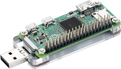
Once you’re connected to the Pi Zero, make sure all updates are installed before making changes to the configuration. First, you will need to modify the config.txt file located at /boot/config.txt and add the following line at the end:
dtoverlay=dwc2
This configuration option enables USB gadgets that will be leveraged shortly. Next, reboot your Pi Zero using the sudo reboot command so that USB gadgets will be enabled.
After you have rebooted, connect back to your Pi Zero where you will need to create a script that will do most of the heavy lifting in the configuration of your USB gadget.
The script here is almost an exact copy of what can be found in this blog post: https://jon.sprig.gs/blog/post/2243
I would encourage you to read it, as the author does a wonderful job explaining the “WHY” for everything — not just with this script, but for most of the process that follows. I have made some modifications to the author’s code to simplify things for our needs, but give all credit to Jon “The Nice Guy” Spriggs.
What you need to do is copy the following script into a file, located at /opt/implant.sh, using the following command:
Sudo nano /opt/implant.sh
#!/bin/bash
# Based on a combination of: http://www.isticktoit.net/?p=1383
#   and: https://www.raspberrypi.org/forums/viewtopic.php?t=260107
#   and: https://gist.github.com/schlarpc/a327d4aa735f961555e02cbe45c11667/c80d8894da6c716fb93e5c8fea98899c9aab8d89
#   and: https://github.com/ev3dev/ev3-systemd/blob/02caecff9138d0f4dcfeb5afbee67a0bb689cec0/scripts/ev3-usb.sh

configfs="/sys/kernel/config/usb_gadget"
this="${configfs}/Implant"

# Configure values
serial="$(grep 'Serial' /proc/cpuinfo | head -n 1 | sed -E -e 's/^Serial\s+:\s+0000(.+)/\1/')"
model="$(grep 'Model' /proc/cpuinfo | head -n 1 | sed -E -e 's/^Model\s+:\s+(.+)/\1/')"
manufacturer="Raspberry Pi Foundation"

# The serial number ends in a mac-like address. Let's use this to build a MAC address.
#   The first binary xxxxxx10 octet "locally assigned, unicast" which means we can avoid
#   conflicts with other vendors.
mac_base="$(echo "${serial}" | sed 's/\(\w\w\)/:\1/g' | cut -b 4-)"
ecm_mac_address_dev="02${mac_base}"  # ECM/CDC address for the Pi end
ecm_mac_address_host="12${mac_base}" # ECM/CDC address for the "host" end that the Pi is plugged into
rndis_mac_address_dev="${mac_base}22"  # RNDIS address for the Pi end
rndis_mac_address_host="32${mac_base}" # RNDIS address for the "host" end that the Pi is plugged into

# Make sure that libComposite is loaded
libcomposite_loaded="$(lsmod | grep -e '^libcomposite' 2>/dev/null)"
[ -z "${libcomposite_loaded}" ] && modprobe libcomposite
while [ ! -d "${configfs}" ]
do
  sleep 0.1
done

# Make the path to the libComposite device
mkdir -p "${this}"

echo "0x0200"                      > "${this}/bcdUSB"       # USB Version (2)
echo "0x1d6b"                      > "${this}/idVendor"     # Device Vendor: Linux Foundation
echo "0x0104"                      > "${this}/idProduct"    # Device Type: MultiFunction Composite Device
echo "0x02"                        > "${this}/bDeviceClass" # This means it is a communications device

# Device Version (this seems a bit high, but OK)
# This should be incremented each time there's a "breaking change" so that it's re-detected
# rather than cached (apparently)
echo "0x4000"                      > "${this}/bcdDevice"

# "The OS_Desc config must specify a valid OS Descriptor for correct driver selection"
#   See: https://www.kernel.org/doc/Documentation/ABI/testing/configfs-usb-gadget
Once you have saved that file, you will need to make it executable, using the command: sudo chmod +x /opt/implant.sh
Next, you need to create a service to run the script automatically. To do that, create a file called Implant.service at /lib/systemd/systems/Implant.service. I used the following command to do so:
sudo nano /lib/system/system/Implant.service
Paste the following script into the file, Implant.service.
[Unit] Description=Start libComposite
[Service] Type=oneshot
ExecStart=/opt/lib_composite.sh
[Install] WantedBy=multi-user.target
Save that file, and then enable the service using the following command:
sudo systemctl enable Implant.service
Now, you will need to reboot your implant.
Once the implant comes back up and you reconnect to it, issue the ifconfig command. You should now see two interfaces, usb0 and usb1.
For reasons that were discussed in the Jon Spriggs blog post linked previously, we configured two interfaces, but we are only really concerned about the usb1 interface, as it is the only interface that will work with a modern Windows host. The usb0 interface is for legacy systems, and, while you may never actually use it, we configured two just in case.
Currently, these interfaces do not have any configuration applied to them, so that is the next step.
Create a file in /etc/network/interfaces.d/ called usb0 and populate it with the following details. You can use the command sudo nano /etc/network/interfaces.d/usb0 to create the file.
allow-hotplug usb0
iface usb0 inet static
  address 192.168.254.2
  netmask 255.255.255.0
Save that file and repeat the process for usb1, by creating the file /etc/network/interfaces.d/usb1 and saving the following content to it.
allow-hotplug usb1
iface usb1 inet static
  address 192.168.255.2
  netmask 255.255.255.0
Having configured the interfaces, now you need to configure a DHCP service to issue an IP address to your target host. For this purpose, we are going to use dnsmasq, which you will need to install with the following command:
sudo apt install dnsmasq
After the successful installation of dnsmasq, you will then need to configure it by editing the dnsmasq configuration file located at /etc/dnsmasq.conf.
Using the following command, you can create the file and save the code below:
sudo nano /etc/dnsmasq.conf
interface=usb0
interface=usb1
bind-interfaces

dhcp-range=usb0,192.168.254.3,192.0.2.3,2h
dhcp-range=usb1,192.168.255.3,192.168.255.3,2h

dhcp-option=option:router
The configuration you just set in the dnsmasq.conf file is pretty simple, but I will provide a high-level overview so that you are not flying blind.
The first three lines are simply setting interfaces within dnsmasq, but the really important stuff is the two dhcp-range lines where the DHCP scopes for each interface is configured and, in this case, we set the DHCP range to be a single IP address: 192.168.25X.3. This allows the target host to receive a single known IP address and that is it!
The last line effectively tells dnsmasq to not set a gateway/router when issuing an DHCP address. We need to do this so that you don’t interfere with the host’s routing… for now.
Next, you need to tell dnsmasq not to bind to the localhost. You can do this by uncommenting the last line of /etc/default/dnsmasq to say DNSMASQ_EXCEPT=”lo”and saving the file.
You can do this using the command sudo nano /etc/default/dnsmasq.
Now dnsmasq is configured, you need to create a shell script and a service to start dnsmasq AFTER the interfaces have come up, as the dnsmasq configuration requires those interfaces being up as a dependency for the configuration to be applied.
Create a script at /opt/dnsmasq.sh and insert the code below using the following command:
sudo nano /opt/dnsmasq.sh
#!/bin/bash
set -x
systemctl disable --now dnsmasq
mv /etc/init.d/dnsmasq /etc/init.d/dnsmasq.initd
sed -i -e "s/Requires=network.target/Requires=network.target sys-subsystem-net-devices-usb0.device sys-subsystem-net-devices-usb1.device/" -e "s~/etc/init.d/dnsmasq ~/etc/init.d/dnsmasq.initd ~g" /lib/systemd/system/dnsmasq.service
Save the file and make the script executable using the following command:
sudo chmod +x /opt/dnsmasq.sh
Then, you need to create a unit file to start dnsmasq at the appropriate time by copying the code below into the file /lib/systemd/system/StartDNSMASQ.service and saving it using the following command:
sudo nano /lib/systemd/system/StartDNSMASQ.service
[Unit]
Description=Start DNSMasq
After=network-online.target

[Service]
Type=oneshot
ExecStart=/bin/bash -c "/opt/dnsmasq.sh"

[Install]
WantedBy=multi-user.target
Next, enable the newly created service using the following command:
sudo systemctl enable StartDNSMASQ.service
Now, reboot your implant.
Drumroll….
Once your implant reboots, in a couple of minutes your host computer should register a new Ethernet device, which, in my case, is Ethernet 4 and is designated as a Remote NDIS Compatible Device. It should get the IP address 192.168.255.3 if everything worked as expected.

Note: You may get a warning like this one below. I have not taken the time to figure out how to avoid this so, yeah. Sorry. It’s expected at this point.
Whew, if you made it this far, I am happy to tell you the hard part is over! Congratulations.
In part four of this blog series, we will pick up from here and finish integrating LoRa out of band communication to create the ultimate physical implant.
Stay tuned.
READ:
You can learn more straight from Tim himself in his Antisyphon Training courses:
Introduction to Cybersecurity in Space Systems (ICSS)
Introduction to Cybersecurity in Space Systems (ICSS): Hardware Edition